Vehicle bumper structure

a technology for bumpers and vehicles, applied in the direction of bumpers, vehicle components, pedestrian/occupant safety arrangements, etc., can solve the problem of difficulty in precisely sensing collisions, and achieve the effect of reducing the variation in the output of load sensors

Inactive Publication Date: 2009-12-31
TOYOTA JIDOSHA KK +2
View PDF3 Cites 36 Cited by
  • Summary
  • Abstract
  • Description
  • Claims
  • Application Information

AI Technical Summary

Benefits of technology

[0006]The present invention provides a vehicle bumper structure that decreases variations in the output of a load sensor.

Problems solved by technology

This makes it difficult to precisely sense the occurrence of collision.

Method used


Image

  • Vehicle bumper structure
  • Vehicle bumper structure
  • Vehicle bumper structure

Examples


first embodiment

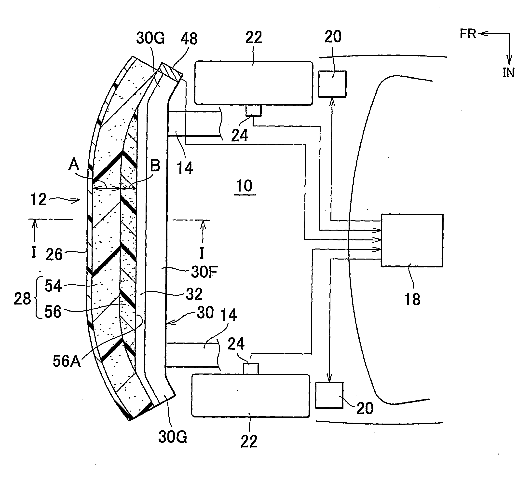
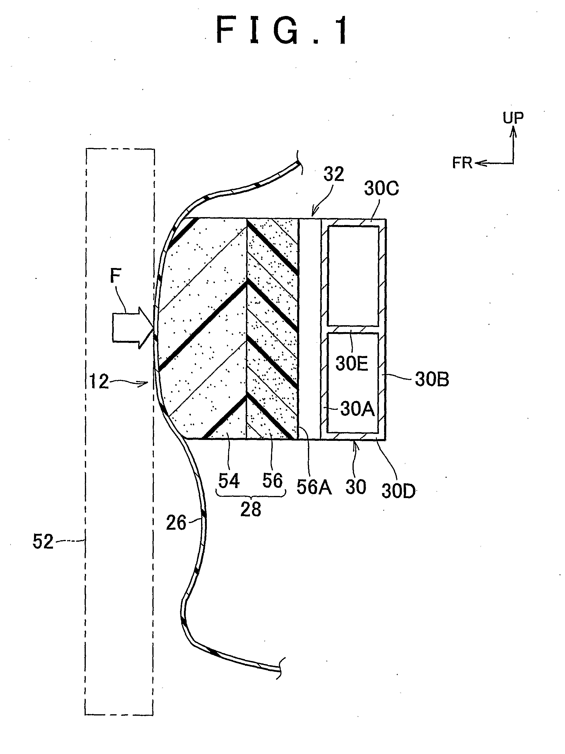
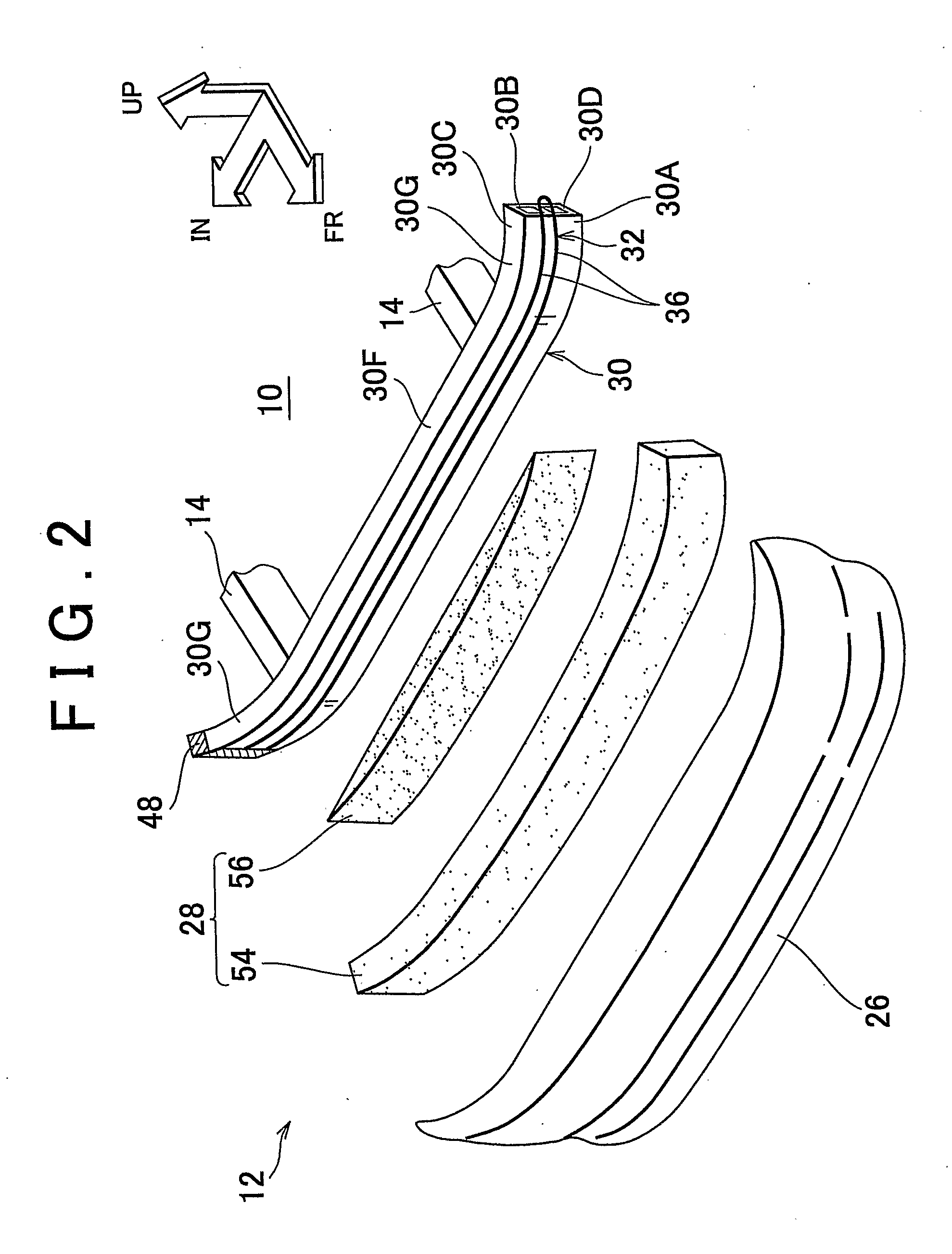
[0068]Hereinafter, there will be described a vehicle bumper structure in accordance with the present invention with reference to FIGS. 1 to 6. In the drawings, the arrow FR represents a vehicle front direction, the arrow UP denotes a vehicle upward direction, and the arrow IN stands for a vehicle inward width direction.

[0069]FIG. 3 is a schematic top view of a front vehicle-body section 10; FIG. 2 is an exploded perspective view of a front-bumper 12 in the front vehicle-body section 10; and FIG. 1 is a vertical sectional view (an enlarged sectional view taken along the line 1-1 in FIG. 3) showing major parts of a vehicle bumper structure in accordance with the first embodiment of the present invention.

[0070]As shown in FIGS. 1 to 3, a pair of left and right front side members 14 is arranged on both lateral sides of the front vehicle-body section 10 to extend in a longitudinal direction of a vehicle. The front side members 14 are jointed at their front ends to a front end portion of ...

second embodiment

[0097]In the vehicle bumper structure of the second embodiment, an on-off sensor that turns on in response to the exertion of a surface pressure equal to or greater than a predetermined value is used as a collision detection sensor 60 arranged at the front surface of the front-bumper reinforcement 30.

[0098]By using an on-off sensor as the collision detection sensor 60, if the hard absorber 58 of the modified example of the first embodiment shown in FIG. 7 is put into use as it is, the flat rear surface of the hard absorber 58 presses the entirety of the collision detection sensor 60, which exerts less surface pressure on the collision detection sensor 60 compared with a case where an irregular rear surface of the hard absorber presses the collision detection sensor 60 under a same impact load. This leaves a possibility that the collision detection sensor 60 will not be turned on.

[0099]Thus, in the present embodiment, a hard absorber 64 provided on its rear surface with an irregulari...

third embodiment

[0112]FIG. 13 is an enlarged vertical sectional view of the front bumper 12 taken at the center of the vehicle. FIG. 14 is an enlarged vertical sectional view of the front bumper 12 taken at one corner region thereof. As illustrated in FIGS. 13 and 14, in the vehicle bumper structure of the third embodiment, a collision detection sensor 70 is offset or off-centered to an upper portion of the front surface of the front wall portion 30A of the front-bumper reinforcement 30. That is, the collision detection sensor 70 has a vertical width smaller than that of the front-bumper reinforcement 30. In the meantime, the collision detection sensor 70 used is a surface pressure sensor for sensing a surface pressure in an analogue fashion and detects the occurrence or absence of collision depending on whether the surface pressure thus sensed exceeds a predetermined threshold value.

[0113]A front-bumper absorber 72 is formed in a single layer structure and not a two-layer structure of a hard and a...


PUM


Abstract

In a vehicle bumper structure, an optical fiber sensor (32) is provided in a vehicle width direction on the front surface of a front-bumper reinforcement (30). A front-bumper absorber (28) is provided in front of the optical fiber sensor (32), the front-bumper absorber (28) formed of a soft absorber (54) and a hard absorber (56). The hard absorber is disposed at the bumper center region where the thickness of the bumper is increased. Accordingly, the thickness of the soft absorber (54) becomes substantially uniform in the vehicle width direction, so that a substantially uniform load is inputted to the optical fiber sensor (32) regardless of the collision position of the bumper with an object. As a result, variations in the output of the load-sensing unit are reduced.

Description

BACKGROUND OF THE INVENTION[0001]1. Field of the Invention[0002]The present invention relates to a vehicle bumper structure that detects a collision with an object such as a pedestrian or the like.[0003]2. Background of the Invention[0004]Japanese Patent Application Publication No. 2000-225907 (JP-A-2000-225907) describes an arrangement in which a load sensor that detects a frontal collision of a vehicle with an object, e.g., a pedestrian is provided. Specifically, a groove extending in the vehicle width direction is formed in a front surface of the front-bumper reinforcement, and an elongated load sensor is placed in the groove, flush with the front surface. On the back surface of the front-bumper absorber, a pair of upper and lower grooves extending in the vehicle width direction are formed. A protruding portion (or a push portion) provided between the upper and the lower groove is disposed to correspond to the load sensor.[0005]However, the vehicle bumper structure described in J...

Claims


Application Information

Patent Timeline
Patent Type & Authority Applications(United States)
IPC IPC(8): B60R19/03
CPCB60R19/483B60R21/0136B60R2019/188B60R2019/1873B60R2019/186B60R19/023B60R19/03B60R2019/1806B60G2401/144B60R2019/1893
Inventor TAKAHASHI, HIROYUKIMIYATA, YUJIROKACHU, RYOTAROTAKAFUJI, TETSUYAKOBAYASHI, SHIGENORIHISHIDA, YASUYUKI
Owner TOYOTA JIDOSHA KK
Why Eureka
Try Eureka