Expander

a technology of expulsion and displacement, applied in the field of expulsion, can solve the problems of large amount of steam leakage, increase in the amount of steam leakage, increase in the dimensions, etc., and achieve the effect of decreasing the dimensions and increasing the outpu

Inactive Publication Date: 2008-08-05
HONDA MOTOR CO LTD
View PDF24 Cites 0 Cited by
  • Summary
  • Abstract
  • Description
  • Claims
  • Application Information

AI Technical Summary

Benefits of technology

[0009]The present invention has been attained in view of the above-mentioned circumstances, and an object thereof is to achieve a further decrease in the dimensions and a further increase in the output of the axial type expander.

Problems solved by technology

Although the vane type expander has the advantage that a high steam expansion ratio can be obtained, a long sealing length between the tip of the vane and the inner periphery of the cam ring is required relative to the volume, and since sealing is difficult, there is a large amount of steam leakage, which is a problem.
In the radial type expander, since the cylinders and the pistons are arranged radially relative to the axis, not only does a fan-shaped dead space formed between adjacent cylinders cause an increase in the dimensions, but is also, if a sliding surface of a rotary valve for distributing the steam among the cylinders is cylindrical and a sliding clearance is provided, there is the problem of an increase in the amount of steam leakage compared with a rotary valve having a flat sliding surface.

Method used


Image

  • Expander
  • Expander
  • Expander

Examples


first embodiment

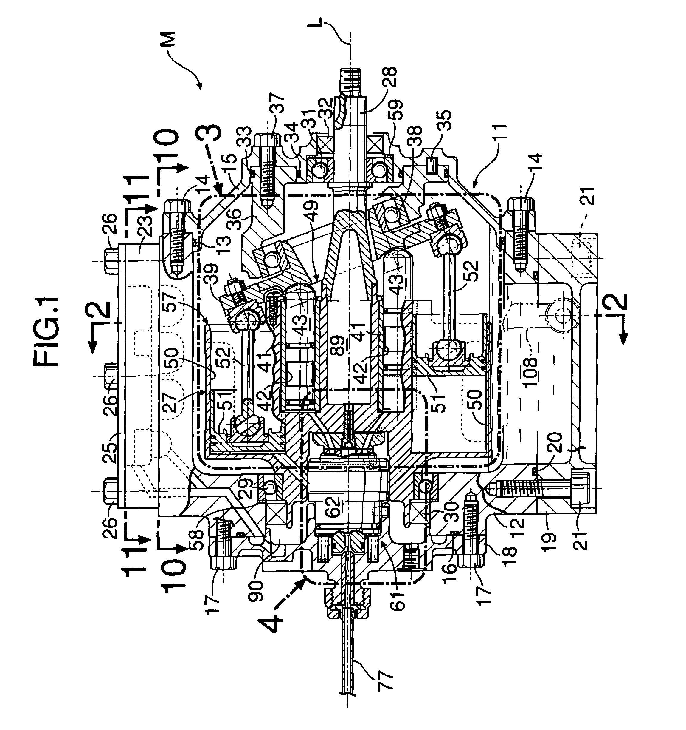
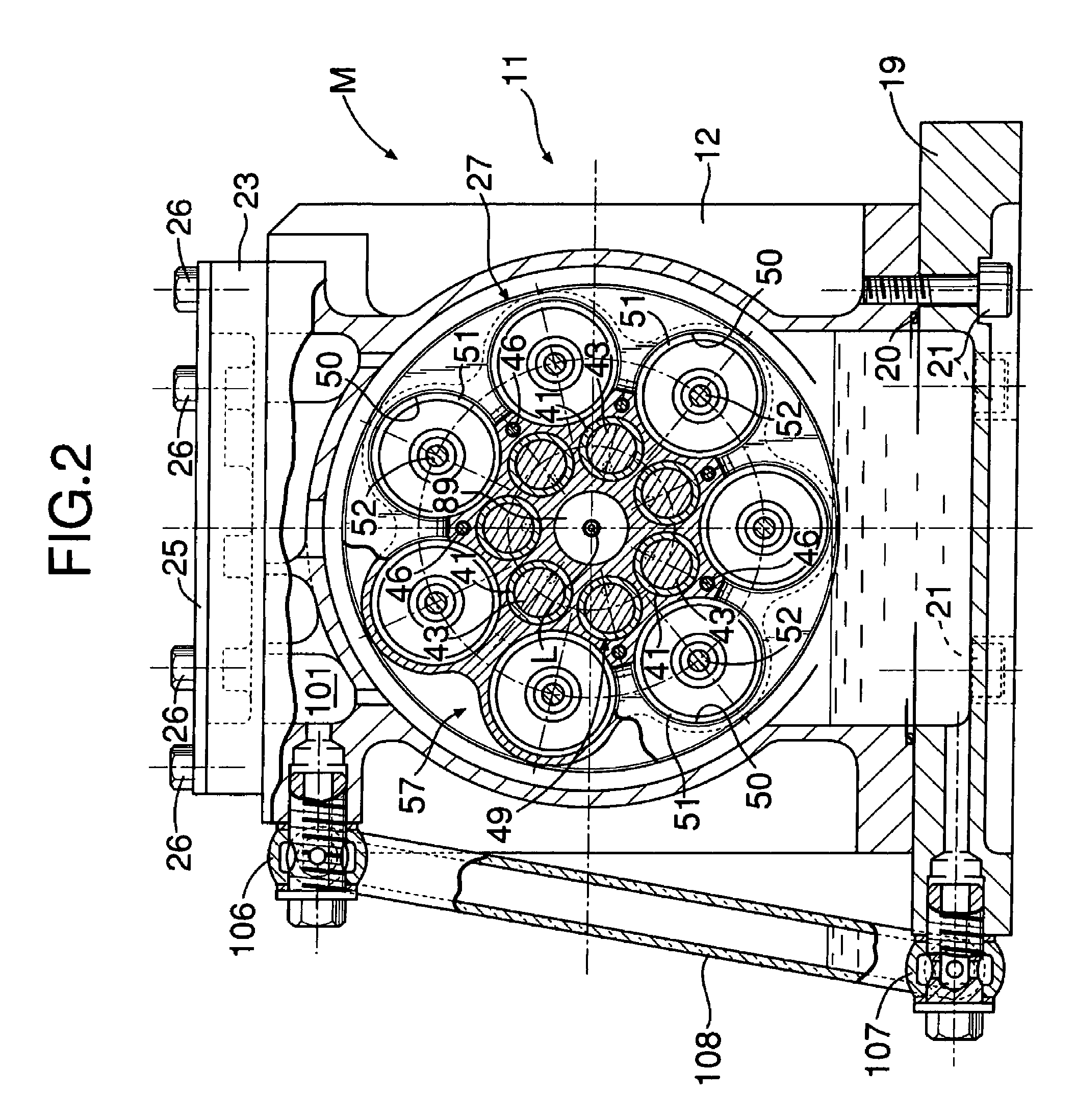
[0022]the present invention is explained below by reference to FIG. 1 to FIG. 18.

[0023]As shown in FIG. 1 to FIG. 3, an expander M of the present embodiment is used in, for example, a Rankine cycle system, and the thermal energy and the pressure energy of high-temperature, high-pressure steam as a working medium are converted into mechanical energy and output. A casing 11 of the expander M is formed from a casing main body 12, a front cover 15 fitted via a seal 13 in a front opening of the casing main body 12 and joined thereto via a plurality of bolts 14, and a rear cover 18 fitted via a seal 16 in a rear opening of the casing main body 12 and joined thereto via a plurality of bolts 17. An oil pan 19 abuts against a lower opening of the casing main body 12 via a seal 20 and is joined thereto via a plurality of bolts 21. Furthermore, a breather chamber dividing wall 23 is superimposed on an upper surface of the casing main body 12 via a seal 22 (see FIG. 12), a breather chamber cove...

second embodiment

[0076]the present invention is now explained by reference to FIG. 19.

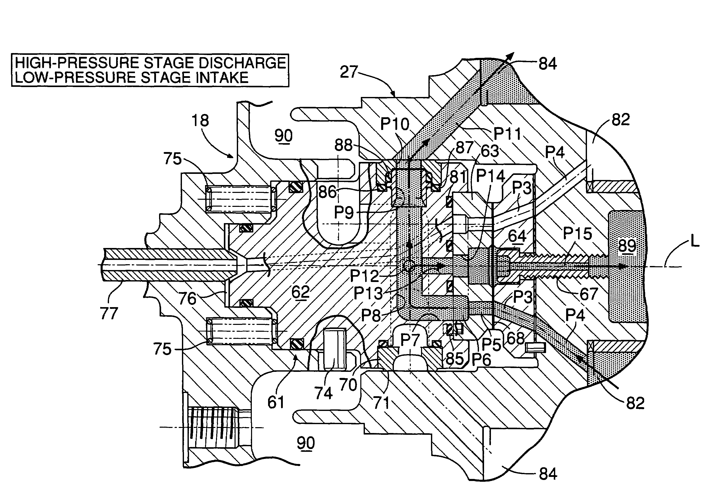
[0077]FIG. 19 shows a sliding surface 68 of a stationary valve plate 63 and corresponds to FIG. 6, which shows the first embodiment. The resilient force of preset springs 75 and the pressure of high-temperature, high-pressure steam acting on a pressure chamber 76 give a sealing surface pressure to the sliding surface 68, but it is difficult to secure a uniform sealing surface pressure over the entire area of the sliding surface 68. This is because the high-temperature, high-pressure steam is supplied to a second steam passage P2 and third steam passages P3 passing through the sliding surface 68, and this high-temperature, high-pressure steam acts to detach the stationary valve plate 63 from a movable valve plate 64 and thereby reduce the sealing surface pressure. On the other hand, medium-temperature, medium-pressure steam is supplied to a fifth steam passage P5 and the third steam passages P3 running through the s...

third embodiment

[0079]the present invention is now explained by reference to FIG. 20.

[0080]The third embodiment is a modification of the second embodiment; a second pressure channel G2 communicating with a second steam passage P2 through which high-temperature, high-pressure steam passes is omitted, and only a first pressure channel G1 communicating with a fifth steam passage P5 through which medium-temperature, medium-pressure steam passes is provided. In accordance with the present third embodiment, not only does the structure become simple compared with the second embodiment, but also the effect of recovering abrasive powder can be enhanced and, moreover, the amount of leakage of steam can be reduced in comparison with the second embodiment.

[0081]Although embodiments of the present invention are explained above, the present invention can be modified in a variety of ways without departing from the spirit and scope thereof.

[0082]For example, in the embodiments the first group of axial piston cylin...


PUM


Abstract

An expander (M) employing steam as a working medium is formed from a first radially inner group of axial piston cylinders (49) arranged annularly on a rotor (27) so as to surround the axis (L) of an output shaft (28), and a second radially outer group of axial piston cylinders (57) arranged annularly so as to surround the first group of axial piston cylinders (49). The first and second groups of axial piston cylinders (49, 57) are driven by a common swash plate (39), and the first and second groups of axial piston cylinders (49, 57) are arranged with circumferentially displaced pitches. High-temperature, high-pressure steam firstly operates the first group of axial piston cylinders (49), then operates the second group of axial piston cylinders (57), and the outputs from the two are combined to drive the output shaft (28). This achieves a further reduction in the size and a further increase in the output of the axial type expander (M).

Description

[0001]This application is the national phase under 35 U.S.C. § 371 of PCT International Application No. PCT / JP02 / 01987 which has an International filing date of Mar. 5, 2002, which designated the United States of America.FIELD OF THE INVENTION[0002]The present invention relates to an expander that includes a casing, an output shaft for outputting a driving force, a rotor integral with the output shaft and rotatably supported in the casing, a plurality of groups of axial piston cylinders arranged annularly in the rotor along the radial direction so as to surround an axis of the output shaft, and a common swash plate fixed to the casing and guiding pistons of the plurality of groups of axial piston cylinders in the direction of the axis.BACKGROUND ART[0003]Japanese Patent No. 2874300 and Japanese Utility Model Registration Application Laid-open No. 48-54702 disclose a piston pump or a piston motor that includes two groups of axial piston cylinders arranged on radially inner and outer ...

Claims


Application Information

Patent Timeline
Patent Type & Authority Patents(United States)
IPC IPC(8): F01B3/00F01B3/02F01B13/04F01B17/04F04B1/22
CPCF01B3/02F04B1/22F01B17/04F01B13/04F04B27/06
Inventor UDA, MAKOTOMAKINO, HIROYUKIOHSONO, KOUHEI
Owner HONDA MOTOR CO LTD
Why Eureka
Try Eureka