Parallel resistor circuit, on-die termination device having the same, and semiconductor memory device having the on-die termination device

Active Publication Date: 2009-12-31
SK HYNIX INC
View PDF5 Cites 2 Cited by
  • Summary
  • Abstract
  • Description
  • Claims
  • Application Information

AI Technical Summary

Benefits of technology

[0026]Embodiments of the invention are directed to providing a parallel resistor circuit that can reduce a resistance variation due to process variations, an on-die termination (ODT) device that can accurately achieve an impedance matching using the parallel resistor circuit, and a semiconductor device including the ODT device.

Problems solved by technology

However, the reduction in the swing width of the signal has a great influence on an external noise, causing the signal reflectance to become more critical at an interface terminal due to impedance mismatch.
Such impedance mismatch is generally caused by an external noise, a variation of a power supply voltage, a change in an operating temperature, a change in a manufacturing process, etc.
The impedance mismatch may lead to a difficulty in high-speed transmission of data and distortion of output data.
Meanwhile, the ODT device does not always include both pull-up and pull-down resistor units.
That is, the resistances of the conventional parallel resistor circuit included in the resistor units 121, 123, 125, 141 and 143 of the ODT device vary with process variations, and thus an error occurs during the ZQ calibration and termination operations, which makes it difficult to achieve an accurate impedance matching after all.

Method used


Image

  • Parallel resistor circuit, on-die termination device having the same, and semiconductor memory device having the on-die termination device
  • Parallel resistor circuit, on-die termination device having the same, and semiconductor memory device having the on-die termination device
  • Parallel resistor circuit, on-die termination device having the same, and semiconductor memory device having the on-die termination device

Examples


Embodiment Construction

[0038]Hereinafter, a parallel resistor circuit, an on-die termination (ODT) device having the same, and a semiconductor memory device having the ODT device in accordance with the invention will be described in detail with reference to the accompanying drawings.

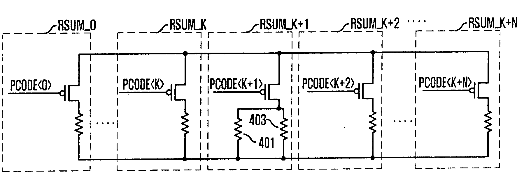
[0039]FIG. 4A is a circuit diagram of a parallel resistor circuit in accordance with an embodiment of the invention.

[0040]The parallel resistor circuit of the invention includes a plurality of parallel resistor units RSUM_0 to RSUM_K+N, which are turned on or off in response to control codes and have at least two resistivities. At least one of the plurality of parallel resistor units RSUM_0 to RSUM_K+N includes resistors with different resistivities that are connected to each other in parallel.

[0041]In FIG. 4A, the plurality of parallel resistor units RSUM_0 to RSUM_K have a first resistivity which is relatively high, whereas the plurality of parallel resistor units RSUM_K+2 to RSUM_K+N have a second resistivity which is relat...


PUM


Abstract

A parallel resistor circuit that can reduce an error of a resistance value, an on-die termination having the same, and a semiconductor device having the on-die termination device. The semiconductor memory device includes a calibration circuit configured to pull up or pull down a predetermined node and compare a voltage of the predetermined node with a reference voltage to generate calibration codes, by using parallel resistor units that are turned on or off in response to the calibration codes. An output driver is configured to terminate a data output node to a pull-up or pull-down level to output data, by using the parallel resistor units. At least one of the parallel resistor units having at least two resistivities includes resistors with different resistivities connected to each other in parallel.

Description

CROSS-REFERENCE TO RELATED APPLICATION[0001]The invention claims priority of Korean patent application number 10-2008-0063123, filed on Jun. 30, 2008, which is incorporated by reference in its entirety.BACKGROUND OF THE INVENTION[0002]The invention relates to a parallel resistor circuit, an on-die termination having the same, and a semiconductor device having the on-die termination device, and more particularly, to a parallel resistor circuit which can reduce an error of a resistance value, an on-die termination having the same, and a semiconductor device having the on-die termination device.[0003]As the operating speed of electrical products is increasing, a swing width of a signal interfaced between semiconductor devices is being gradually reduced for minimizing a delay time taken for signal transmission. However, the reduction in the swing width of the signal has a great influence on an external noise, causing the signal reflectance to become more critical at an interface termina...

Claims


Application Information

Patent Timeline
IPC IPC(8): H03K19/003H01C13/00
CPCH01C1/16H03K19/0005H01C13/02G11C7/1048G11C2207/2254
Inventor CHOI, CHANG-KYU
Owner SK HYNIX INC
Why Eureka
Try Eureka