Antenna system

a beamformer and antenna technology, applied in the direction of antennas, antenna details, electrical equipment, etc., can solve the problems of destructive combination of signals from other antenna elements than the first antenna element providing input to the beamformer at the connecting port, and achieve the reduction the maximisation of the magnitude of the resultant signal, and the reduction of the loss of signal between the antenna element and the connecting point

Inactive Publication Date: 2009-12-31
APPLE INC
View PDF2 Cites 48 Cited by
  • Summary
  • Abstract
  • Description
  • Claims
  • Application Information

AI Technical Summary

Benefits of technology

[0017]The connecting port provides access to signals at an individual antenna element without the need to remove the beamformer, which may for example be beneficial in situations where access to the beamformer is difficult or costly or where the beamformer is physically integrated with the antenna elements.
[0018]Constructively combining signals is a process of combining signals substantially in phase so that the magnitude of the resultant signal is maximised. Destructively combining signals is a process of combining signals in such a way that they cancel, so that the magnitude of the resultant signal is minimised.
[0019]Preferably, the beams formed by the beamformer are orthogonal beams. The benefit of forming orthogonal beams is that the signal loss between the antenna element and the connecting point is minimised.

Problems solved by technology

combining said at least two beam outputs at the connecting port such that signals from antenna elements other than the first antenna element providing input to the beamformer are destructively combined at the connecting port; and

Method used


Image

  • Antenna system
  • Antenna system
  • Antenna system

Examples


Embodiment Construction

[0054]In general, the present invention is directed to methods and apparatus that enhance the capacity of wireless communications between a base station and remote stations. The invention will be described in the context of a cellular wireless system, but it is to be understood that this example is chosen for illustration only and that other applications of the invention are possible.

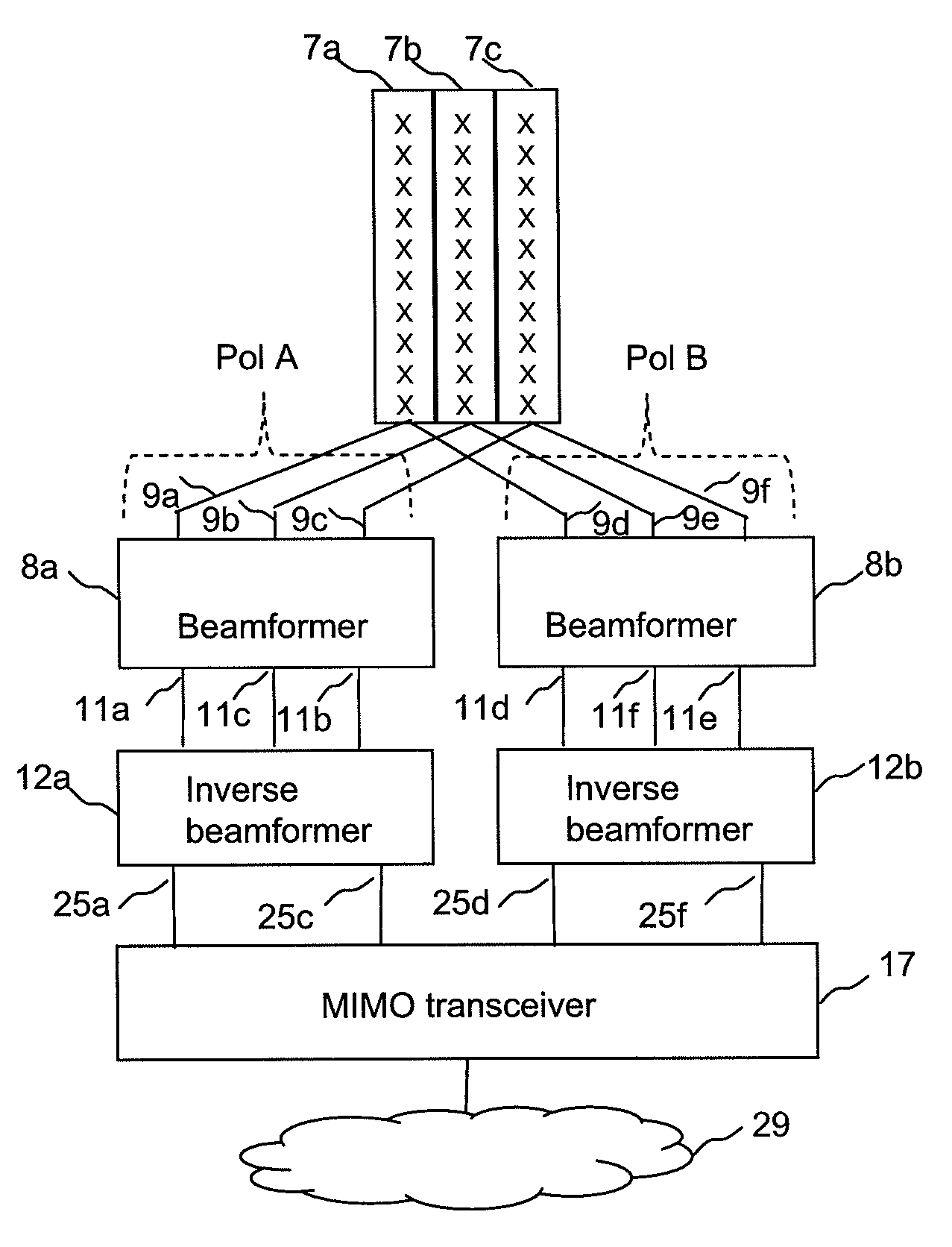
[0055]FIG. 5 illustrates a first embodiment of the invention, which relates to a beamformer that produces two beams from a three element antenna array. Three antenna elements 7a, 7b and 7c, which may be typically vertical columns of antenna elements, are connected to beamformer 8, which may typically be integrated with the antenna elements and may be within the same enclosure. In a one deployment, the antenna elements 7a, 7b, and 7c and beamformer 8 will be sited on a tower at a cellular radio cell site. Three such integrated units would be deployed at a cell site, so that each may give coverage to an a...


PUM


Abstract

Embodiments of the invention are concerned with improvements to antenna systems, in particular beamforming antenna systems. Embodiments provide an improved beamformer arrangement for receiving and transmitting of signals by antenna elements. Embodiments are particularly well suited to use for transceiving of radio signals by base stations, such as are commonly found in cellular networks. In one aspect, embodiments provide a beamformer for use in processing signals received, or transmitted, by a first antenna element, the beamformer comprising a first set of ports and a second set of ports, wherein the first set of ports is connected to at least two antenna elements including said first antenna element and the second set of ports is connected to a connecting port, wherein the beamformer is arranged to generate at least first and second output beams from signals received from the at least two antenna elements and to transform signals received via the second set of ports into signals for transmission by the at least two antenna elements, wherein the beamformer is arranged to combine said generated at least first and second output beams at the connecting port such that said signals from said first antenna element are constructively combined at the connecting port, and to combine said at least first and second output beams at the connecting port such that signals from antenna elements other than the first antenna element are destructively combined at the connecting port, wherein the connecting port is arranged so as to provide access to individual said signals received, or transmitted, by said at least two antenna elements. In particularly preferred arrangements the first set of ports is connected to three or four antenna elements.

Description

FIELD OF THE INVENTION[0001]The present invention relates generally to antennas for wireless data communications networks, and more specifically to beamforming antenna systems.BACKGROUND OF THE INVENTION[0002]Modern wireless communications systems place great demands on the antennas used to transmit and receive signals, especially at cellular wireless base stations. Antennas are required to produce a carefully tailored radiation pattern with a defined beamwidth in azimuth, so that, for example, the wireless cellular coverage area has a controlled overlap with the coverage area of other antennas.[0003]In addition to a defined azimuth beam, such antennas are also required to produce a precisely defined beam pattern in elevation; in fact the elevation beam is generally required to be narrower than the width of the azimuth beam.[0004]It is conventional to construct such antennas as an array of antenna elements so as to form the required beam patterns. Such arrays require a feed network ...

Claims


Application Information

Patent Timeline
Patent Type & Authority Applications(United States)
IPC IPC(8): H01Q3/00
CPCH01Q1/246H01Q3/00H01Q25/002H01Q3/26
Inventor ADAMS, DAVID NEILDEANE, PETERHALL, STEVEN RAYMOND
Owner APPLE INC
Why Eureka
Try Eureka