Reconfigurable electromagnetic antenna

a technology of electromagnetic antennas and electromagnetic antennas, which is applied in the direction of fluid pressure measurement, liquid/fluent solid measurement, peptide measurement, etc., can solve the problems of intrinsic losses affecting the effectiveness of the antenna, the range of impedance variations of the reconfiguration mode is limited, and the effect of switching and impedance loss

Active Publication Date: 2009-12-31
SAMSUNG ELECTRONICS CO LTD
View PDF8 Cites 25 Cited by
  • Summary
  • Abstract
  • Description
  • Claims
  • Application Information

AI Technical Summary

Benefits of technology

[0020]The invention makes it possible to produce an antenna with a radiating element that can vary in volume.
[0021]These variations make it possible to cause the properties of the antenna to evolve dynamically and obtain the desired properties of the antenna in frequency, in polarization or even in radiation pattern. The reconfiguration of the antenna in frequency, in polarization or in radiation pattern is continuous and reversible.
[0022]The application of electrical voltage between the electrodes of the electrode matrix makes it possible to drive the movement and the deformation of the fluid substance in contact with the electrode matrix in a continuous manner.
[0023]The electro-wetting phenomena also allows for a deformation of the fluid substance in all dimensions.

Problems solved by technology

These two reconfiguration modes present drawbacks.
In the case where impedances connected to certain points of the antenna are made to vary, a continuous variation of the frequency or of the radiation pattern is obtained, but it is limited by the variation ranges of the impedances used.
Furthermore, the devices used for the reconfiguration (switches and impedances) present intrinsic losses that affect the effectiveness of the antenna.

Method used


Image

  • Reconfigurable electromagnetic antenna
  • Reconfigurable electromagnetic antenna
  • Reconfigurable electromagnetic antenna

Examples


first embodiment

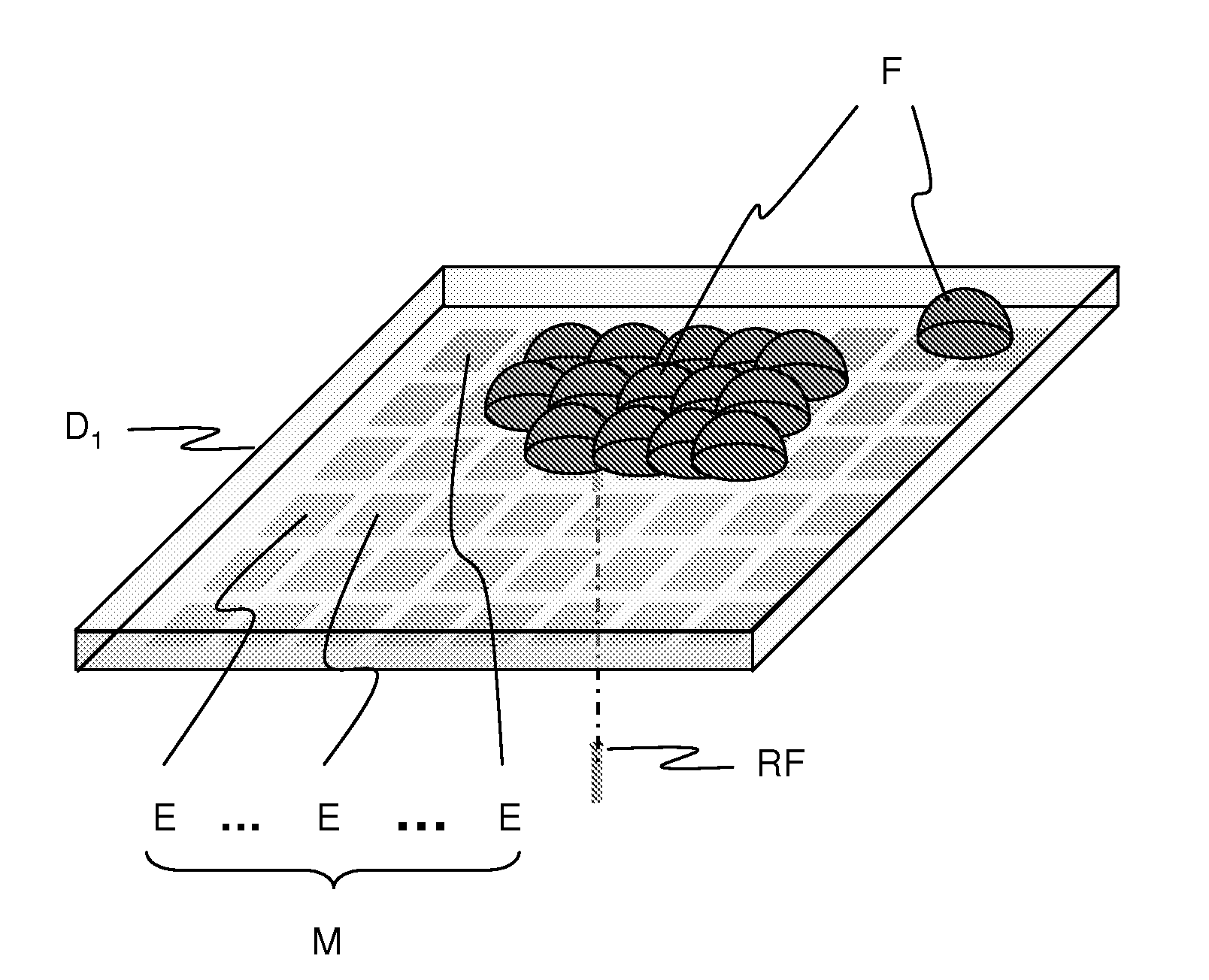
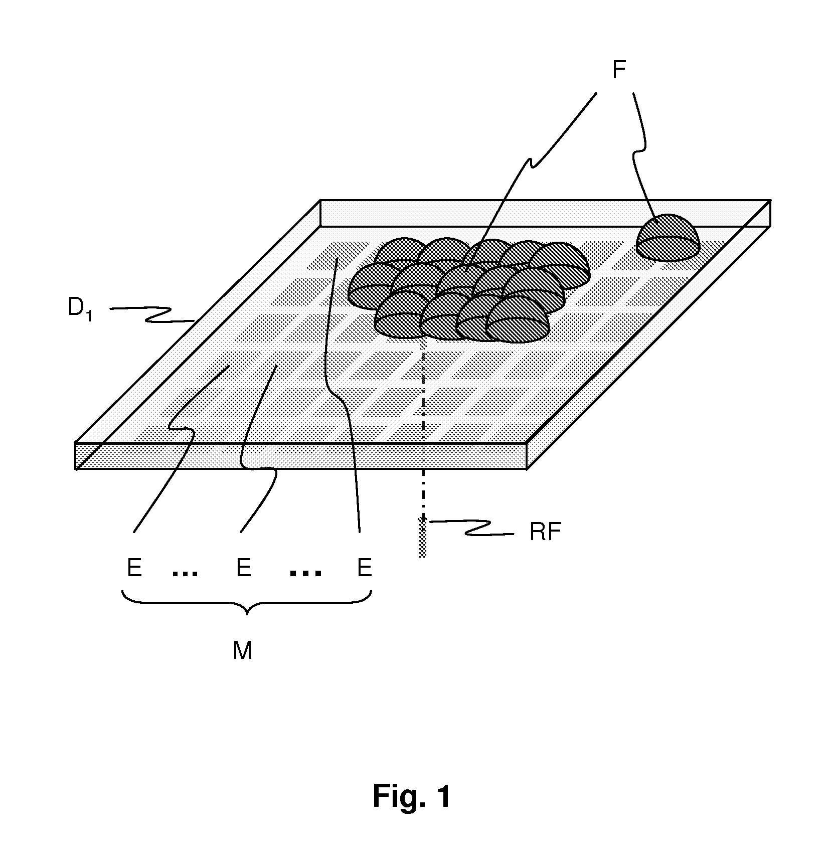
[0053]FIG. 1 represents a perspective view of an antenna according to the invention.

[0054]The reconfigurable electromagnetic antenna according to the invention comprises a fluid substance F that conducts electricity.

[0055]The fluid substance F takes the form of one or more drops.

[0056]The antenna also comprises a radiofrequency port RF making it possible to transmit and receive radiofrequency signals. The RF port is a conductive element that is in contact with at least one drop of the fluid substance.

[0057]The portion of the fluid substance F in contact with the radiofrequency port RF corresponds to the active radiating element of the antenna. This portion of the fluid substance F in contact with the radiofrequency port consists of at least one drop of fluid substance F. When the radiating element is made up of a number of drops, all the drops do not need to be in contact with the radiofrequency port RF. It is then enough for one drop to be in contact with the radiofrequency port RF...

second embodiment

[0079]FIG. 4 represents a perspective view of an antenna according to the invention.

[0080]In this second embodiment, the antenna comprises a reservoir R which contains a fluid substance F′.

[0081]The reservoir R is capable of releasing a portion, notably in the form of drops, of the fluid substance F′ intended for an electrode matrix M′ consisting of electrodes E′. The fluid substance F′ is separated from the electrode matrix M′ by a dielectric D′1.

[0082]The reservoir R can also recover a portion, in particular in the form of drops, of the fluid substance F′ originating from the electrode matrix M′.

[0083]The drops of the fluid substance F′ are moved from the reservoir R to the electrode matrix M′ or vice versa from the electrode matrix M′ to the reservoir R by electro-wetting along a channel C of electrodes. The channel C of electrodes links the reservoir R to the electrode matrix M′.

[0084]A port R′F′ passes through the electrode matrix M′, the dielectric D′1 and is in contact with a...


PUM

PropertyMeasurementUnit
volumeaaaaaaaaaa
dielectricaaaaaaaaaa
sizeaaaaaaaaaa

Abstract

A reconfigurable electromagnetic antenna which comprises a radiating element consisting of a fluid substance that conducts electricity, the volume of the fluid substance being variable and that also comprises a matrix of electrodes on which the fluid substance is moved by electro-wetting.
The properties of the antenna in frequency, polarization or even in radiation pattern evolve dynamically. The reconfiguration of the antenna in frequency, in polarization or in radiation pattern is continuous and reversible.

Description

CROSS-REFERENCE TO RELATED PATENT APPLICATION[0001]This application claims the benefit of French Patent Application No. 08 54343, filed on Jun. 27, 2008, in the French Institute of Industrial Property, the entire contents of which is incorporated herein by reference.BACKGROUND OF THE INVENTION[0002]The present invention is situated in the field of reconfigurable electromagnetic antennas.[0003]The proliferation of wireless and mobile applications, in a radiofrequency signal propagation environment constrained by multiple interference and signal attenuation phenomena, requires a great adaptation of the terminals with minimum impact on, among other things, the complexity, the size, the weight, the autonomy or even the cost of these terminals.[0004]The development of reconfigurable electromagnetic antennas for these terminals hopes to overcome these constraints.[0005]There are several types of reconfigurable antennas. For example, there are antennas that can be reconfigured in frequency...

Claims


Application Information

Patent Timeline
Patent Type & Authority Applications(United States)
IPC IPC(8): H01Q1/36H01Q1/40B01D57/02
CPCH01Q3/01H01Q1/364
Inventor DREINA, EMMANUELPONS, MICHELBERENGUER, MARC
Owner SAMSUNG ELECTRONICS CO LTD
Why Eureka
Try Eureka