Cyclo-converter and methods of operation

a cycloconverter and cycloconverter technology, applied in the direction of ac-dc conversion, ac-electronic conversion, electric variable regulation, etc., can solve the problems of complex single-stage design, poor overall conversion efficiency, and the sum total of the total conversion loss, so as to facilitate soft switching of the switch

a cycloconverter and cycloconverter technology, applied in the direction of ac-dc conversion, ac-electronic conversion, electric variable regulation, etc., can solve the problems of complex single-stage design, poor overall conversion efficiency, and the sum total of the total conversion loss, so as to facilitate soft switching of the switch

US20090323380A1Active Publication Date: 2009-12-31EATON INTELLIGENT POWER LTD

Image

  • Cyclo-converter and methods of operation
  • Cyclo-converter and methods of operation
  • Cyclo-converter and methods of operation

Examples


Embodiment Construction

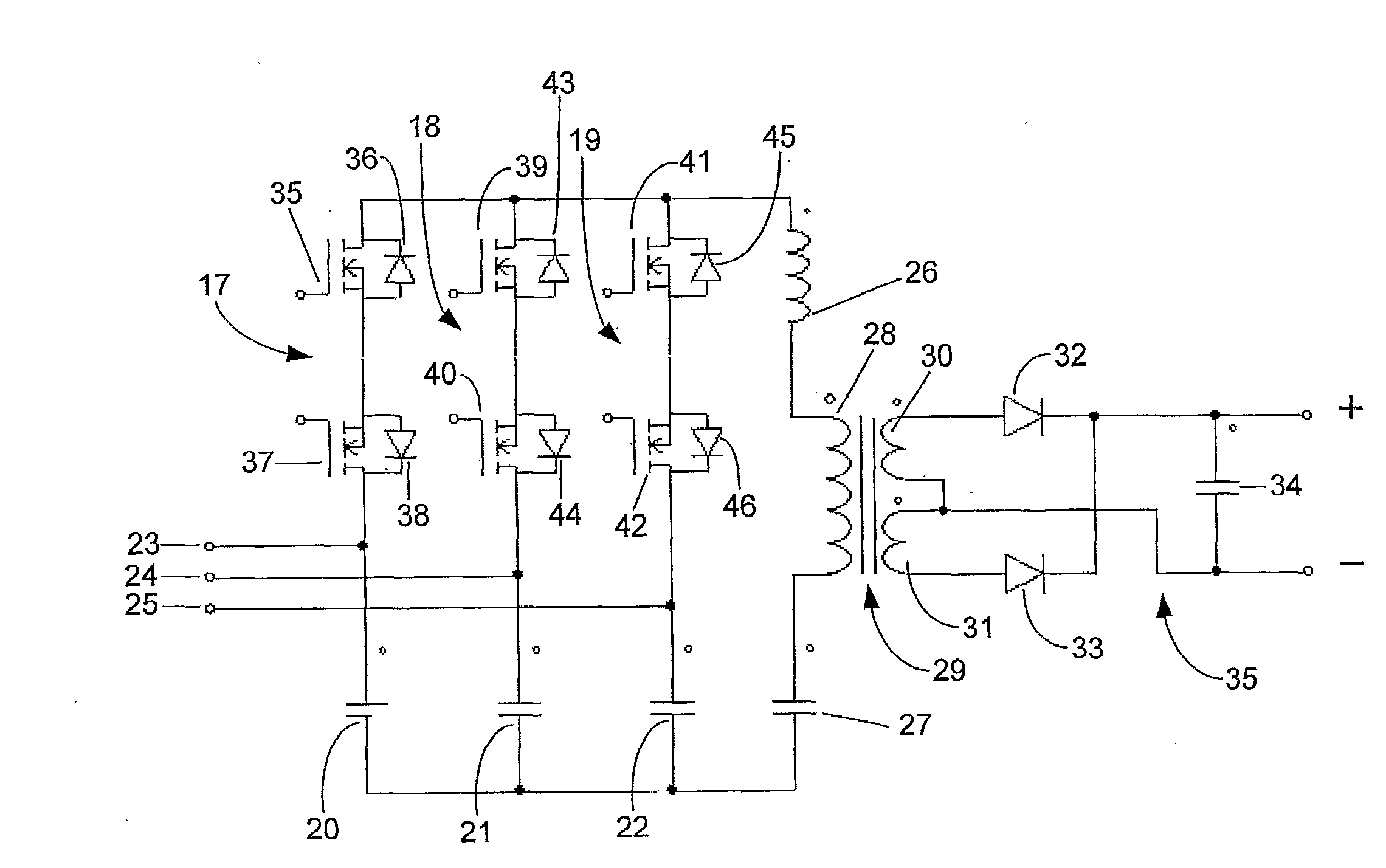
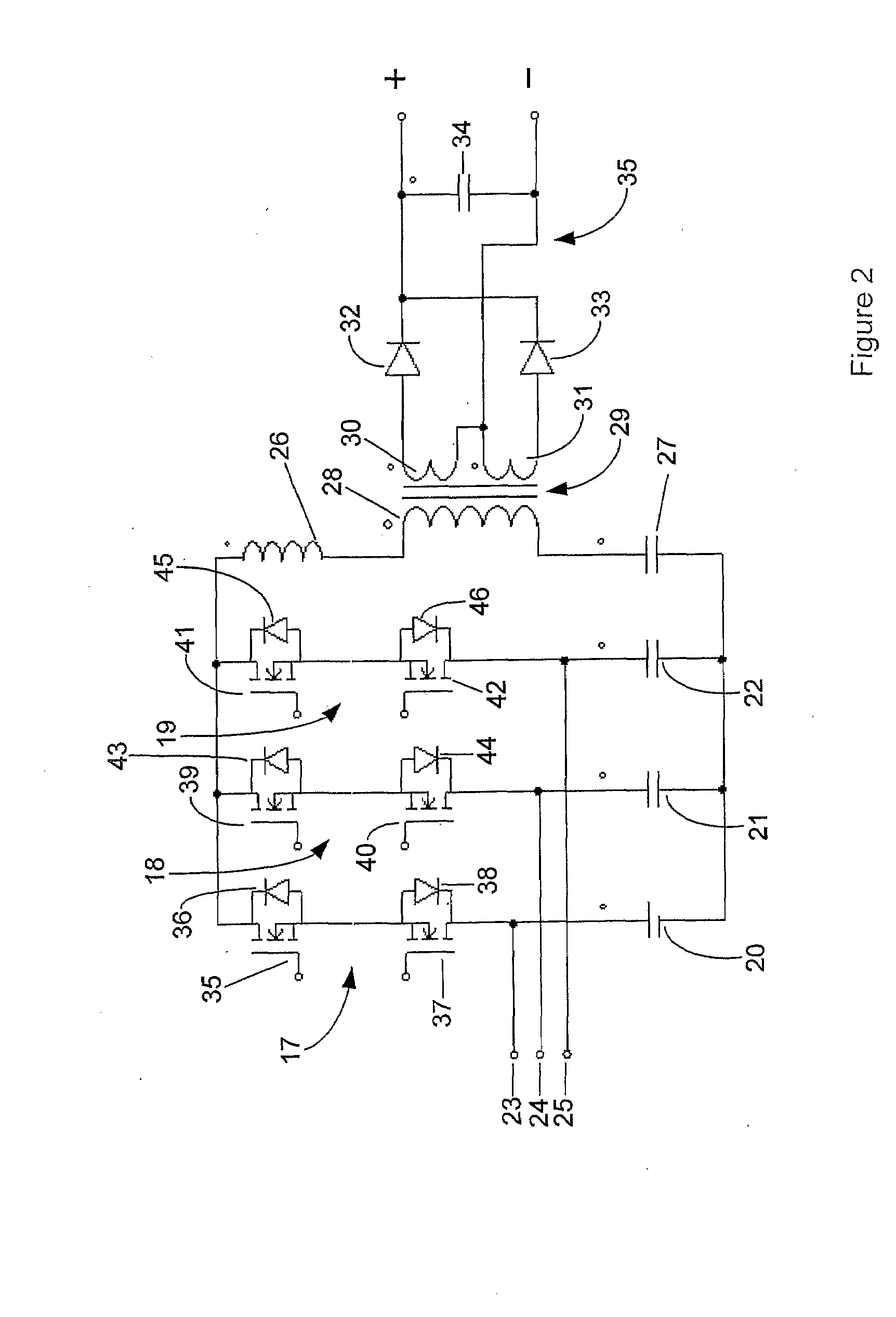
[0040]FIG. 2 shows a half bridge cyclo-converter according to a first embodiment. The cyclo-converter includes bidirectional switches 17 to 19 and capacitors 20 to 22 forming the half bridge. Switch 17 consists of MOSFET 35 in parallel with body diode 36 in series with MOSFET 37 in parallel with body diode 38. Switch 17 has four states:[0041]1. on (MOSFETs 35 and MOSFET 37 on);[0042]2. off (MOSFET's 35 and 37 off)[0043]3. forward diode (MOSFET 37 on switching in body diode 36)[0044]4. reverse diode (MOSFET 35 on switching in body diode 38)

[0045]Switches 18 and 19 are similarly configured. By utilizing the four switching states full resonant switching can be achieved as will be described.

[0046]Three phase supply lines 23 to 25 provide a three phase AC supply to the half bridge. The output of the cyclo-converter drives an LLC resonant circuit consisting of inductor 26, capacitor 27 and primary coil 28 of transformer 29. Output coils 30 and 31 are connected via diodes 32 and 33 and cap...


PUM


Abstract

A three phase full resonant cyclo-converter suitable for converting a three phase AC supply to a DC output. In one embodiment the cycloconverter controls switching frequency to control converter output and adjusts phase on times for power factor correction. A switching sequence is employed which provides resonant switching to reduce losses and component ratings. The converter provides high conversion efficiency with a simple power component design.

Description

FIELD OF THE INVENTION[0001]This invention relates to a cyclo-converter and to methods of operating a cyclo-converter. More particularly, although not exclusively, the invention relates to a three phase full resonant cyclo-converter suitable for converting a three phase AC supply to a DC output. Whilst the converter of the present invention may find particular application in telecommunications power supplies it will be appreciated that it may find application in a wide range of applications.BACKGROUND OF THE INVENTION[0002]In applications such as telecommunications power supplies converters must meet requirements as to Total Harmonic Distortion, harmonic current limits, isolation etc. whilst also achieving high conversion efficiencies. The performance requirements for isolated AC to DC switched mode power supplies for use in telecommunications and large computer applications have to a large extent been met through the adoption of two-stage power supply designs. The first power conve...

Claims


Application Information

Patent Timeline
31 Dec 2009
Publication
US20090323380A1
IPC
H02M7/06
CPC
H02M1/4216; H02M1/4233; H02M1/425; H02M1/4258; Y02B70/145; H02M7/219; Y02B70/126; Y02B70/1441
Inventors
HARRISON, MICHAEL JOHN