Dynamic load balancing

a wireless communication network and dynamic load technology, applied in the field of dynamic load balancing in the wireless communication network, can solve the problems of increasing the cost of wireless equipment, ineffective planning practice, and high cost for service providers, and achieve the effect of reducing cell congestion, reducing the number of subscribers in handover zones, and narrowing the coverage area

Active Publication Date: 2009-12-31
VIAVI SOLUTIONS INC
View PDF100 Cites 132 Cited by
  • Summary
  • Abstract
  • Description
  • Claims
  • Application Information

AI Technical Summary

Benefits of technology

[0010]The narrowing of the coverage area reduces cell congestion by optimizing the coverage area according to actual subscriber distribution within the wireless communication network. Additionally, by narrowing of the coverage areas, for congested areas, overlapping of coverage areas and the number of subscribers in handover zones are reduced. Also, narrowing of the coverage area for some cells increases the range of the coverage areas for other cells. Improvement in the cell congestion and quality of service can be determined based on, for example, a dropped call percentage and a congestion ratio.

Problems solved by technology

Dimensioning fixed resources to satisfy traffic demand for busy hours is an ineffective planning practice and is very expensive for service providers since the resources for every site are often over estimated to meet traffic demand that may occur only in limited time durations.
However, complex signal processing is required in the base stations, which increases the cost of wireless equipment.
However, detailed implementation is left unspecified by the standard.
Additionally, because of the complexity of the implementation, most of base station vendors have decided not to implement beamforming in their initial products.

Method used


Image

  • Dynamic load balancing
  • Dynamic load balancing
  • Dynamic load balancing

Examples


Embodiment Construction

[0024]In the description that follows, numerous details are set forth in order to provide a thorough understanding of the invention. It will be appreciated by those skilled in the art that variations of these specific details are possible while still achieving the results of the invention. Well-known elements and processing steps are generally not described in detail in order to avoid unnecessarily obscuring the description of the invention.

[0025]In the drawings accompanying the description that follows, often both reference numerals and legends (labels, text descriptions) may be used to identify elements. If legends are provided, they are intended merely as an aid to the reader, and should not in any way be interpreted as limiting.

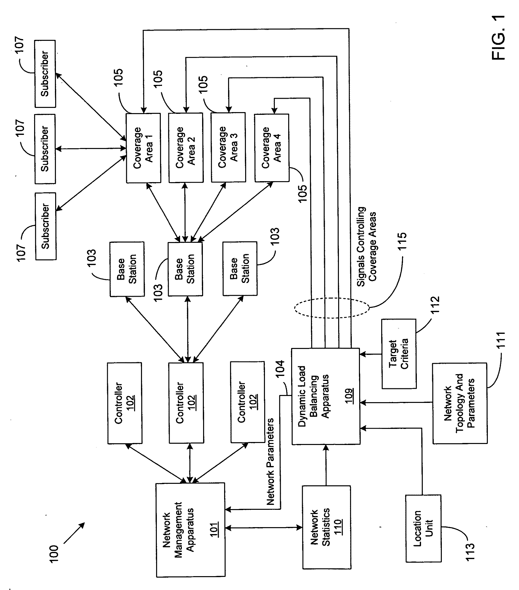
[0026]FIG. 1 is a system for implementing dynamic load balancing in a wireless communication network in accordance with an embodiment of the invention. In particular, the wireless communication network 100 illustrated in FIG. 1 includes a dynamic load bal...


PUM


Abstract

A method, program, system and apparatus perform dynamic load balancing of coverage areas in a wireless communication network. The dynamic load balancing is performed by evaluating cell congestion based on location information of subscribers in the wireless communication network, collecting network parameters related to the wireless communication network and altering network parameters based on the evaluated cell congestion. After the network parameter is altered, the coverage areas are narrowed. Improvements in cell congestion and quality of server are then determined based on the narrowing of the coverage areas. Altering of the plurality of network parameters and evaluating of the cell congestion are performed continuously until a target quality of service is achieved.

Description

CROSS-REFERENCE TO RELATED APPLICATIONS[0001]This application claims priority to U.S. provisional patent application No. 61 / 075799 entitled “Method and Apparatus for Dynamic Load Balancing in Wireless Communication Networks” filed on Jun. 26, 2008, the contents of which are fully incorporated herein by reference.BACKGROUND OF THE INVENTION[0002]1. Field of the Invention[0003]The present invention generally relates to dynamic load balancing in a wireless communication network. In particular, the present invention relates to dynamic load balancing by altering the coverage areas and optionally altering network parameters such as frequencies of one or a plurality of coverage areas.[0004]2. Description of the Related Art[0005]Network planning relies on static approaches for site locations and dimensioning of the radio resources to meet a specified traffic demand at busy hours. Dimensioning fixed resources to satisfy traffic demand for busy hours is an ineffective planning practice and is...

Claims


Application Information

Patent Timeline
Patent Type & Authority Applications(United States)
IPC IPC(8): H04W72/00H04W4/00G08C15/00H04L12/26
CPCH04L41/5025H04W64/00H04W28/18H04W28/08H04W16/08H04W28/0289
Inventor TRIGUI, HAFEDHCUTHILL, RICKKUSYK, RICHARD GLENN
Owner VIAVI SOLUTIONS INC
Why Eureka
Try Eureka