
Method for determining a depth map from images, device for determining a depth map

a depth map and image technology, applied in image analysis, instruments, computing, etc., can solve the problems of high accuracy, large amount of computing power, and accuracy only as good, and achieve the effect of eliminating bias and good results

Inactive Publication Date: 2009-12-31
KONINKLIJKE PHILIPS ELECTRONICS NV
View PDF0 Cites 45 Cited by
  • Summary
  • Abstract
  • Description
  • Claims
  • Application Information

AI Technical Summary

Benefits of technology

[0018]Preferably the sum of the unit vectors is a weighted sum, wherein the weight for each unit vectors within the calculation is a function of distance to the point of interest. This will improve the accuracy. The disparity value of a point of interest is more likely to be similar to the disparity value of near-neighboring points than to points further away from the point of interest.
[0019]Preferably the set of matching comprises one or more matching windows for which the point of interest is eccentrically located in respect of the matching window. While square blocks are the most commonly used shapes for matching windows, eccentrically positioned shapes for matching windows are more suitable for locking on particular image features such us horizontal and vertical edges. The fact that they are not centered at the point of interest in the image allows at least one of the windows to properly match near occluding boundaries.
[0022]In preferred embodiments the number of matching windows is four and the matching windows form a cross. A cross is a simple arrangement, which has shown to give good results.
[0023]In another preferred embodiment the number of matching windows is eight, wherein the windows are comprised of two foursomes, one foursome being the left hand or right hand version of the windows in the other foursome, each forming a cross. Using one foursome of matching windows may introduce a slight left to right or right to left bias. By using two foursomes this bias can be eliminated.In another embodiment the matching windows are substantially triangular.

Problems solved by technology

This requires a high accuracy, which requires large amounts of computing power.
Even so, the accuracy is only as good as the particular choice of matching windows, i.e. if a particular problem is associated with the choice of matching windows, the problem will persist.
If the size of the matching window employed is large this may result in blurred depth maps with inaccurate boundaries and a loss of fine details.
Using smaller windows on the other hand, while reducing calculating power and being good, could lead to a method prone to noise.
The result of matching with relatively small windows will be noisy depth maps but containing important small image features.
For such calculation only a limited calculating power is needed.

Method used


Image

  • Method for determining a depth map from images, device for determining a depth map
  • Method for determining a depth map from images, device for determining a depth map
  • Method for determining a depth map from images, device for determining a depth map

Examples


Embodiment Construction

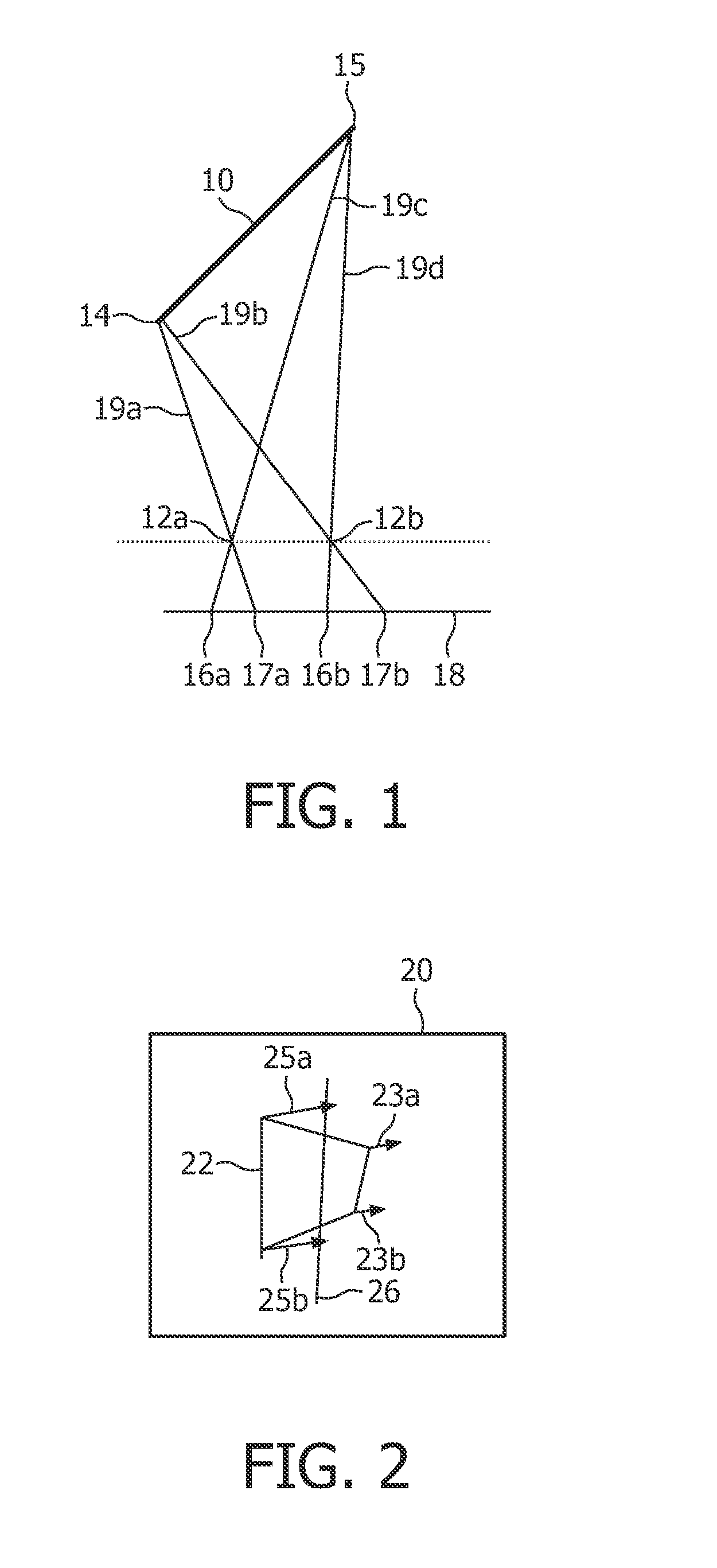
[0038]FIG. 1 shows the geometry of a part of an image 10 and two orientations 12a,b. A part of an image may be for instance a person, or any object within the image. The present invention relates to a method for providing a depth map for an image. A depth map can be seen as attributing a z-value, i.e. a depth value, to points of objects. When images of a scene containing the part of an image 10 are obtained using point projection from different orientations 12a,b, the position where points 14, 15 on the part of an image will be visible in the image are projections 16a,b, 17a,b of points 14, 15. The projections can be illustrated by drawing lines 19a-d from the points 14, 15 through the orientations 12a,b to an image plane 18. For setting out the basic principles, the orientations 12a,b have been selected in a plane parallel to the image plane 18, but the invention is not limited to such a selection of orientations 12a,b. The intersections between these lines 19a-d and the image plan...


PUM


Abstract

Window based matching is used to determine a depth map from images obtained from different orientations. A set of matching windows is used for points of the image for which the depth is to be determined. A provisional depth map is generated wherein to each point more than one candidate disparity value is attributed. The provisional depth map is filtered by a surface filtering wherein at least the z-component of a norm of a sum of unit vectors pointing from the candidate disparity values for neighboring points to a point of interest.

Description

FIELD OF THE INVENTION[0001]The invention relates to a method for determining a depth map from images obtained from different orientations using window-based matching for a point of the image. The invention also relates to a device for determining a depth map from images obtained from different orientations using window-based matching for a point of the image.DESCRIPTION OF PRIOR ART[0002]For a number of applications it is desirable to determine a depth map from images. Examples of such applications include systems that make it possible to compute images of the scene viewed from interactively controllable orientations, image compression, inspection etc. The task of recovering depth maps from stereo imagery is often crucial for a wide range of applications such as 3D displays, quality control at manufacturing, autonomous navigation and object recognition. Herein, depth of a point in an image refers to the distance between the viewpoint and the plane through the point and perpendicula...

Claims


Application Information

Patent Timeline
Patent Type & Authority Applications(United States)
IPC IPC(8): G06T7/00G06K9/00
CPCG06T7/0065G06T7/55G06T17/00G06T7/60
Inventor BOUGHORBEL, FAYCAL
Owner KONINKLIJKE PHILIPS ELECTRONICS NV
Learn More