System and Method for Optical Continuous Detection of an Analyte In Bloodstream

an optical continuous and analyte technology, applied in the field of blood assays, can solve the problems of reducing the overall usefulness and effectiveness of the blood analyzer, unable to provide real or present-time data of the analyte of interest present in the blood stream, and conventional blood analyzers failing to detect the clinically meaningful rate of change in analyte concentration

Inactive Publication Date: 2009-12-31
TYCO HEALTHCARE GRP LP
View PDF23 Cites 15 Cited by
  • Summary
  • Abstract
  • Description
  • Claims
  • Application Information

AI Technical Summary

Problems solved by technology

However, known blood analyzers of the type aforementioned present a major drawback which detracts from their overall usefulness and effectiveness.
In particular, the conventional blood analyzer is incapable of providing real or present time data of the analyte of interest present in the blood stream.
In clinical situations where the concentration of an analyte of interest in the blood can be expected to change rapidly (e.g. myocardial infarction), conventional blood analyzers fail to detect the clinically meaningful rate of change in analyte concentration.
Moreover, the conventional blood analyzer is limited in that it can only indicate the presence of the analyte at the moment when the sample of blood was drawn.
However, performing multiple assays is overly invasive to the patient.
In addition, this solution is also imperfect since there is a possibility that occurrence of the biological event may be missed, or its detection delayed by as long as the time interval between successive blood draws.
This particular problem is acutely prevalent in the field of monitoring of acute myocardial infarction patients.
Due to the relatively long time periods between assays, a true infarction patient with biological signs of infarction may, as a result, wait for many hours before the signs are detected.
Consequently, there is a delay in providing therapy to the patient.

Method used


Image

  • System and Method for Optical Continuous Detection of an Analyte In Bloodstream
  • System and Method for Optical Continuous Detection of an Analyte In Bloodstream
  • System and Method for Optical Continuous Detection of an Analyte In Bloodstream

Examples


Embodiment Construction

[0023]Particular embodiments of the present disclosure are described hereinbelow with reference to the accompanying drawings. In the following description, well-known functions or constructions are not described in detail to avoid obscuring the present disclosure in unnecessary detail.

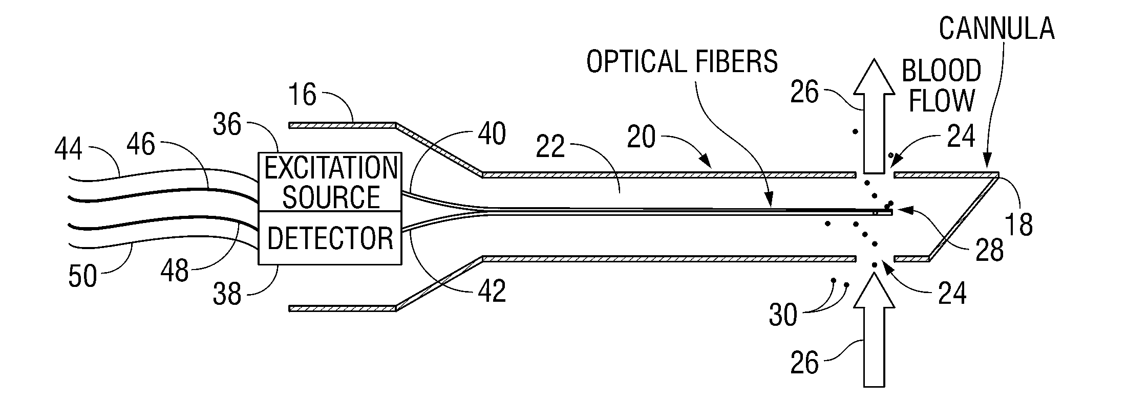
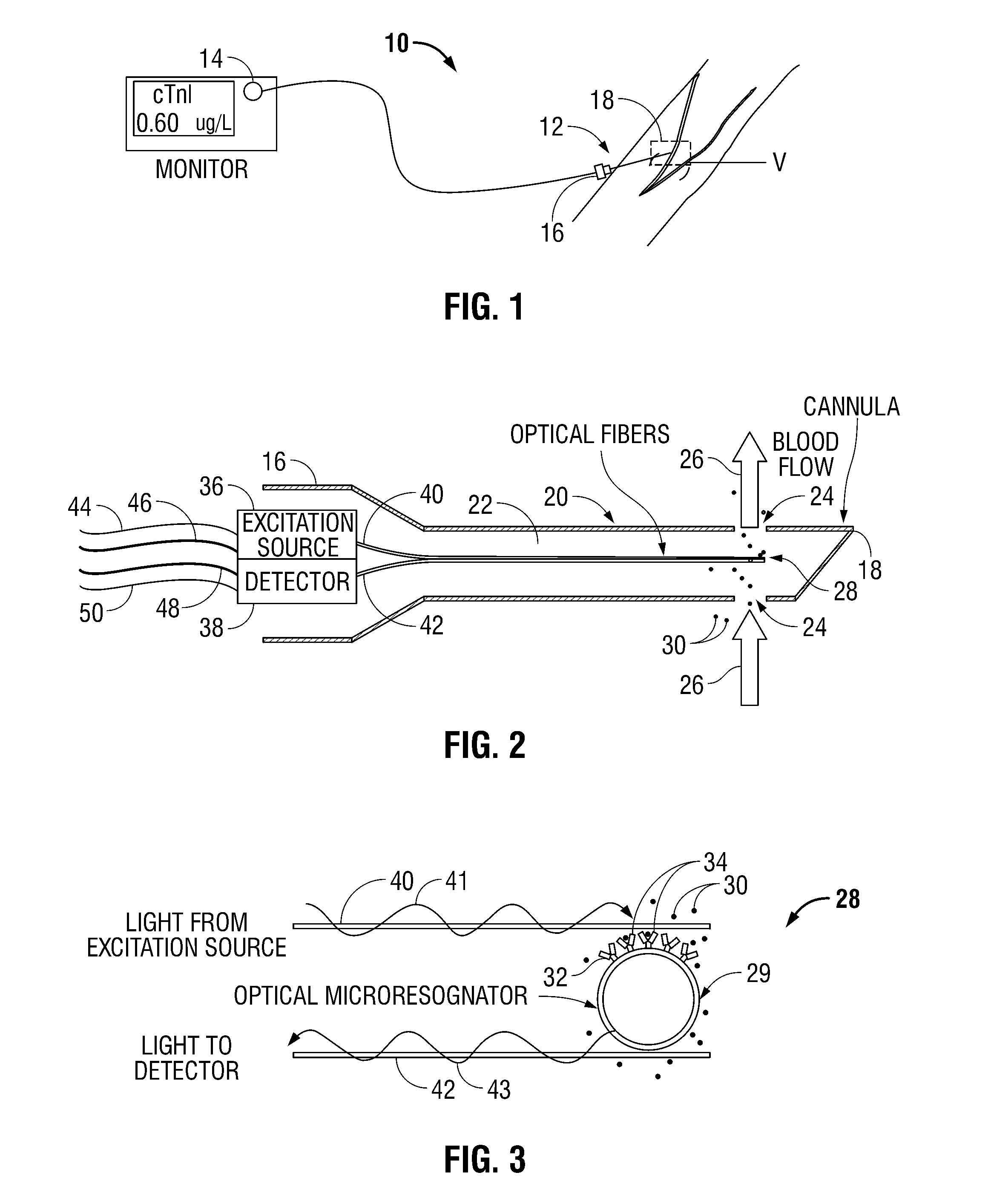
[0024]Referring now to FIGS. 1-3, blood analyzer 10 in accordance with the principles of the present disclosure is illustrated. Generally, blood analyzer 10 includes an access member or a probe 12 and a monitor 14 in electrical communication with the probe 12. The probe 12 has a proximal end 16 and a distal end 18. The probe 12 may be any tubular structure (e.g., a catheter or a cannula) having a housing 20 and a lumen 22 defined therein and one or more ports 24 at the distal end 18 thereof adapted to provide fluid access to the lumen 22. The distal end 18 of the probe 12 is inserted into a blood vessel “V” to allow for the blood to flow into the lumen as illustrated by directional arrows 26. It is env...


PUM


Abstract

A method for performing a blood assay includes the steps of positioning an optical biosensor in fluid communication with a blood vessel whereby blood from the blood vessel contacts the biosensor. The biosensor includes at least one material adapted to bind to an analyte. The method also includes the steps of detecting a change in at least one optical property of the biosensor resulting from binding of the at least one material with the analyte and transmitting a continuous signal representative of the change in at least one optical property of the biosensor to a display module to provide real time analysis by a clinician.

Description

CROSS-REFERENCE TO RELATED APPLICATION[0001]The present application claims the benefit of U.S. Provisional Application Ser. No. 61 / 076,225 entitled “SYSTEM AND METHOD FOR OPTICAL CONTINUOUS DETECTION OF AN ANALYTE IN BLOODSTREAM” filed on Jun. 27, 2008 by Peter Meyer, the entire disclosure of which is incorporated by reference herein.BACKGROUND[0002]1. Technical Field[0003]The present disclosure relates to a system and method for performing blood assays. In particular, the present disclosure is directed to in vivo optical biosensors configured to continuously monitor blood to detect the presence and / or concentration of an analyte of interest.[0004]2. Background of Related Art[0005]Various types of blood analyzers for detecting specific analytes of interest (e.g., proteins) are known in the art. A conventional blood analyzer utilizes a sensor to detect the presence of the analyte and optionally determines the concentration thereof. In vitro methods are usually utilized to obtain a bl...

Claims


Application Information

Patent Timeline
Patent Type & Authority Applications(United States)
IPC IPC(8): A61B5/1459
CPCA61B5/0084A61B5/14503A61B5/14546A61B5/6848G01N2021/7789G01N21/77G01N33/54373G01N2021/7776G01N21/553
Inventor MEYER, PETER F.
Owner TYCO HEALTHCARE GRP LP
Why Eureka
Try Eureka