
Methods for determining an initial AINS heading

Active Publication Date: 2009-12-31
APPLANIX
View PDF5 Cites 27 Cited by
  • Summary
  • Abstract
  • Description
  • Claims
  • Application Information

AI Technical Summary

Benefits of technology

[0006]The present invention rapidly determines the initial heading of an AINS to an accuracy of 5 degrees or better and thereby significantly simplifies and shortens the initialization and fine alignment time in kinematic applications including airborne, marine, land vehicle, and man-portable inertial navigation systems, by eliminating the need to refer to and read an external heading reference such as a magnetic compass. It is an object of this invention to provide a means for estimating an azimuth heading shortly after power-up without reference to a magnetic or other reference compass and to operate with a system such as a man-portable application in which large centripetal accelerations typically do not occur.
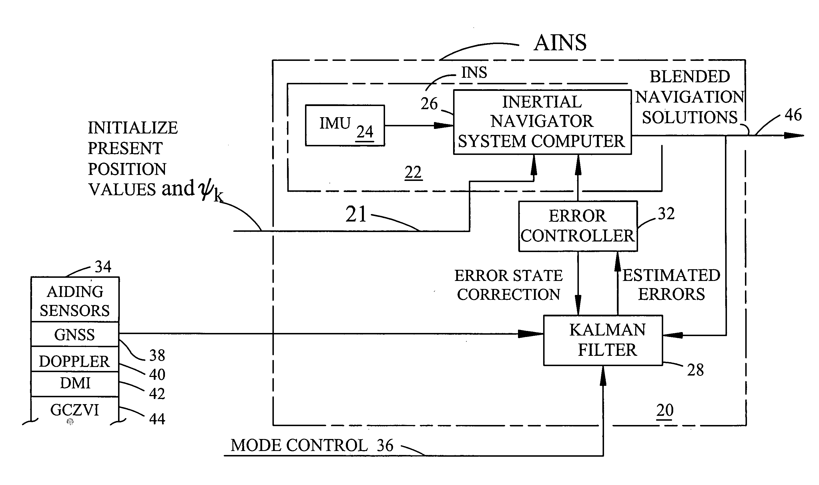
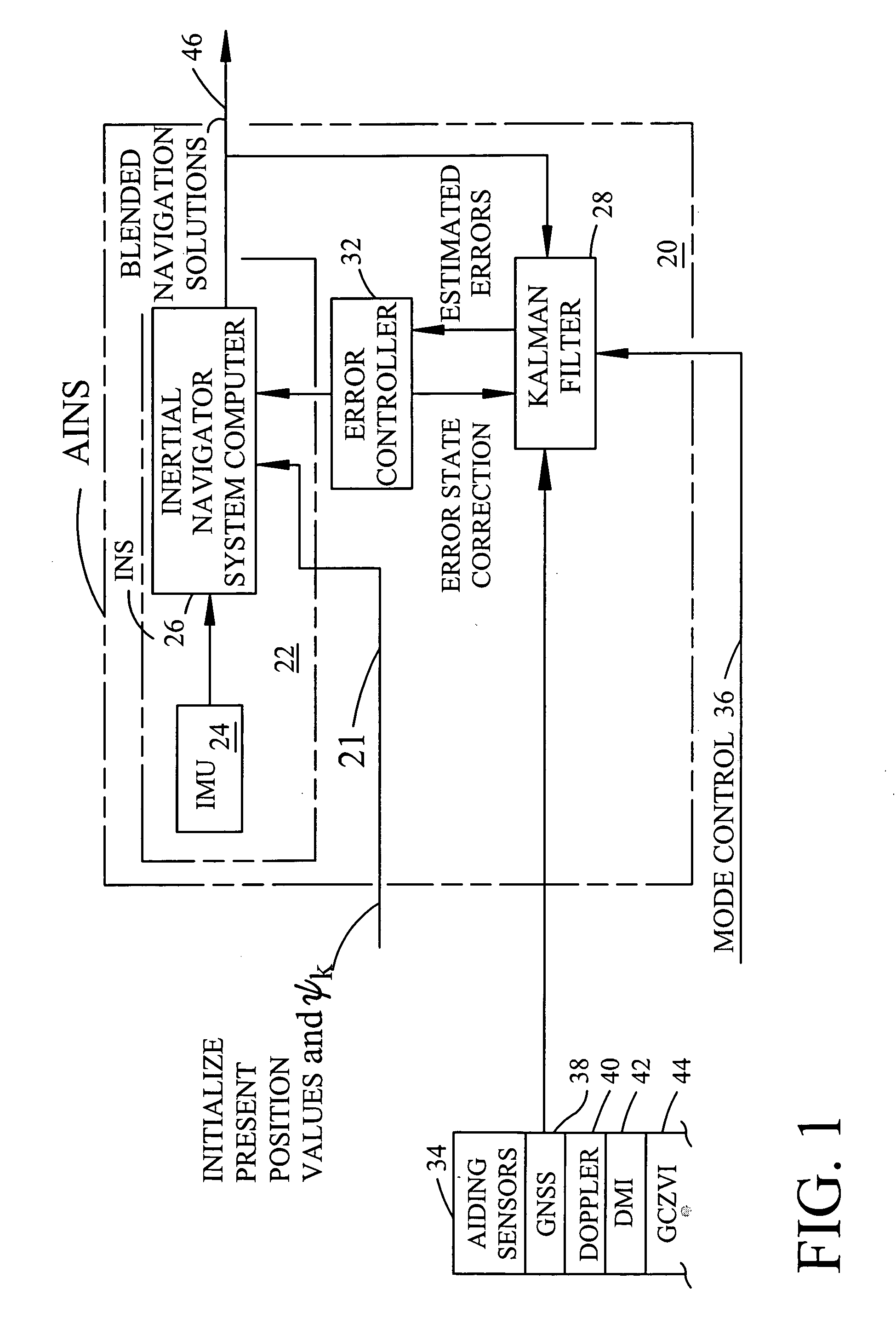
[0007]The present invention is used with an AINS with a GPS receiver input and a Kalman filter. The method of this innovation is used after applying power, and before the start of fine alignment or gyrocompassing, After power is applied, The operator moves or walks the system around for a short period of time. During this phase, a GPS receiver continues to provide aiding navigational data that is recorded concurrently with AINS data.

Problems solved by technology

However, external heading sensors can have disadvantages.
A multi-antenna GNSS-based attitude determination system is expensive and the GNSS antennas must be separated by as large a distance as possible, which prohibits its use in small vehicle or pedestrian navigation applications.
For man-portable mobile applications, where the dynamics experienced are smaller, in-motion alignment requires a long and possibly unacceptable convergence time.

Method used


Image

  • Methods for determining an initial AINS heading
  • Methods for determining an initial AINS heading
  • Methods for determining an initial AINS heading

Examples


Embodiment Construction

[0032]Reference will now be made in detail to various embodiments, and examples of which are illustrated in the accompanying drawings. While the subject matter will be described in conjunction with these embodiments, it will be understood that they are not intended to limit the subject matter to these embodiments. On the contrary, the subject matter described herein is intended to cover alternatives, modifications and equivalents, which may be included within the spirit and scope as defined by the appended claims. Furthermore, in the following description, numerous specific details are set forth in order to provide a thorough understanding of the subject matter. In other instances, well-known methods, procedures, objects, and circuits have not been described in detail as not to unnecessarily obscure aspects of the subject matter.

Notation and Nomenclature

[0033]Unless specifically stated otherwise as apparent from the following discussions, it is appreciated that throughout the prese...


PUM


Abstract

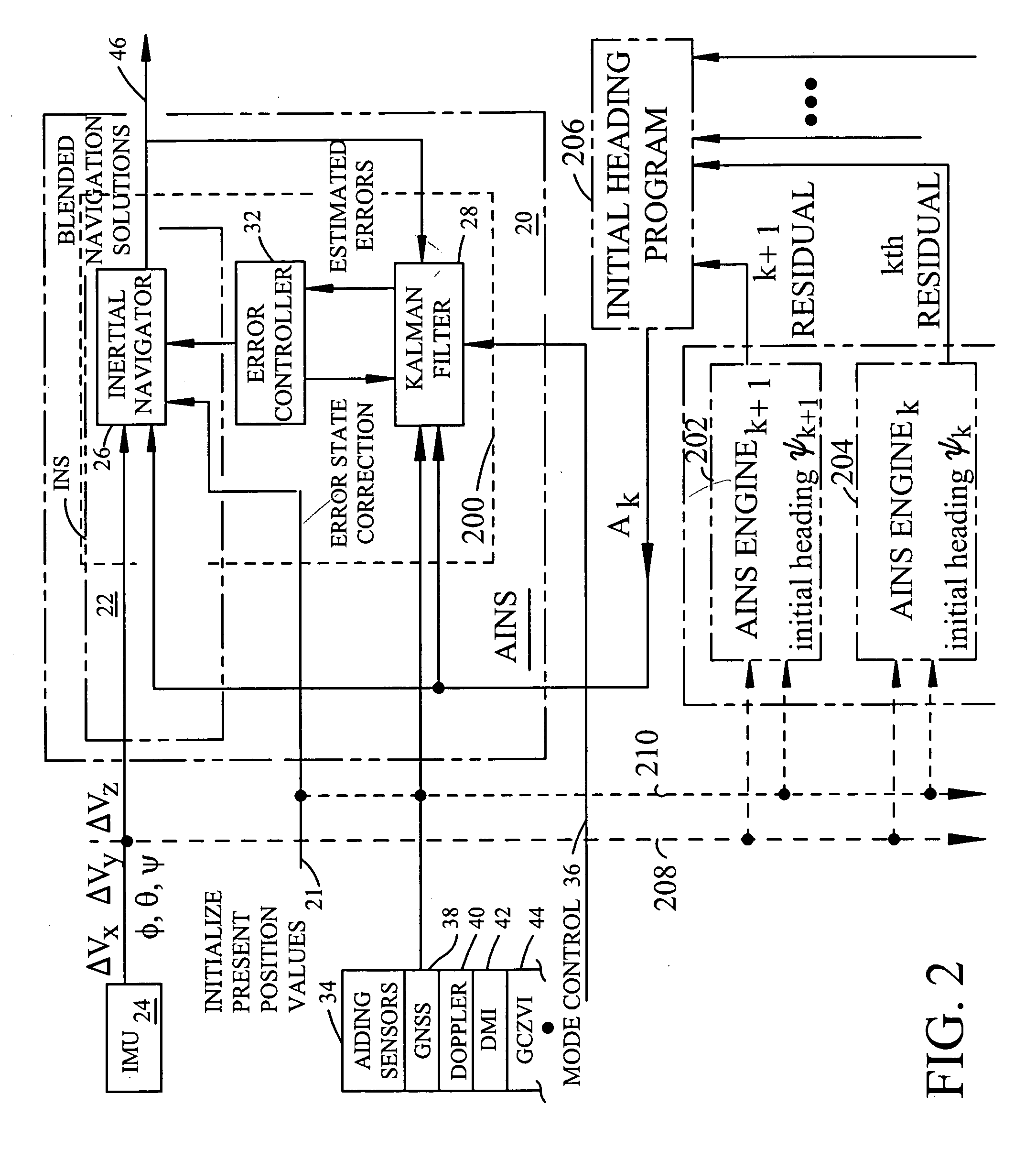
Two methods for determining a best initial heading estimate for use in an AINS system, while recording position data values and in-motion data values, assigning incremental changes to indexed heading ψk, calculating a set of time indexed present AINS position values and a corresponding set of time indexed absolute horizontal position measurement residual values, recording the absolute maximum time indexed horizontal position measurement residual and the corresponding value of ψk returning to the step of assigning an incremental increase to a next value to indexed heading ψk up to 360 degrees, identifying the maximum time indexed horizontal position measurement residual and corresponding ψk, followed by identifying the ψk having the smallest absolute maximum horizontal position measurement residual as Ak Second method uses a circular array of AINS ENGINES each with a different ψk running in parallel and finding smallest horizontal position measurement residual for Ak.

Description

FIELD OF THE INVENTION[0001]This invention relates to the field of aided inertial navigation system (AINS) and more particularly to the field of selecting a best estimate of the system wander angle or system heading before the start of fine alignment or gyrocompassing. The present invention provides a best indexed angle Ak (a best initial heading estimate) selected from an indexed array of estimated indexed wander angles ψk for use as an initial estimate of a wander angle and for subsequent use during in stationary or in-motion gyro-compassing alignment during which a precise wander angle ψ is calculated. A principal purpose of the invention method is the elimination of the need for a magnetic compass input or other external heading estimate of the wander angle for use as an input at the start of a gyrocompassing routine or process. In addition to use in precision surveying systems such as those that have an AINS that is aided by a GNSS, the present invention can be applied in low d...

Claims


Application Information

Patent Timeline
IPC IPC(8): G01C23/00G06F19/00
CPCG01C23/00
Inventor WANG, JAU-HSIUNG
Owner APPLANIX
Learn More