
Apparatus and method for encoding and decoding an encoded audio signal using temporal noise/patch shaping

a technology of temporal noise and patch shaping, applied in the field of audio coding/decoding, can solve the problems of large bitrate constraints on the storage or transmission of audio signals, large amount of coders' time and effort, and relatively complex analysis/synthesis stages, so as to minimize the effect of low bitrate perceptual annoyan

Active Publication Date: 2015-10-08
FRAUNHOFER GESELLSCHAFT ZUR FOERDERUNG DER ANGEWANDTEN FORSCHUNG EV
View PDF18 Cites 29 Cited by
  • Summary
  • Abstract
  • Description
  • Claims
  • Application Information

AI Technical Summary

Benefits of technology

The patent describes a method for reducing artifacts in video compression by using complex TNS / TTS filtering. This helps to avoid the issue of temporal aliasing, which can occur when samples are not properly aligned. The method also allows for better matching between different source regions and helps to stabilize the video frame. Additionally, the method includes a technique for pruning and stabilizing tile selection to avoid artifacts caused by fast-changing source regions. Overall, this method improves the quality and stability of video compression.

Problems solved by technology

Storage or transmission of audio signals is often subject to strict bitrate constraints.
In the past, coders were forced to drastically reduce the transmitted audio bandwidth when only a very low bitrate was available.
All these methods involve transformation of the data into a second domain apart from the Modified Discrete Cosine Transform (MDCT) and also fairly complex analysis / synthesis stages for the preservation of HF sinusoidal components.
This introduces additional processing delays, may introduce artifacts due to tandem processing of firstly transforming from the spectral domain into the frequency domain and again transforming into typically a different frequency domain and, of course, this also necessitates a substantial amount of computation complexity and thereby electric power, which is specifically an issue when the bandwidth extension technology is applied in mobile devices such as mobile phones, tablet or laptop computers, etc.
However, BWE techniques are restricted to replace high frequency (HF) content only.
Furthermore, they do not allow perceptually important content above a given cross-over frequency to be waveform coded.
Therefore, contemporary audio codecs either lose HF detail or timbre when the BWE is implemented, since the exact alignment of the tonal harmonics of the signal is not taken into consideration in most of the systems.
This leads to complications of synchronization, additional computational complexity and increased memory requirements.
Particularly, if a bandwidth extension system is implemented in a filterbank or time-frequency transform domain, there is only a limited possibility to control the temporal shape of the bandwidth extension signal.
This can lead to unwanted pre- or post-echoes in the bandwidth extension spectral range.
In order to increase the temporal granularity, shorter hop-sizes or shorter bandwidth extension frames can be used, but this results in a bitrate overhead due to the fact that, for a certain time period, a higher number of parameters, typically a certain set of parameters for each time frame has to be transmitted.
However, the so generated spectrum has a lot of spectral gaps.
The high frequency portion, however, can be strongly uncorrelated due to the fact that there might be a different high frequency noise on the left side compared to another high frequency noise or no high frequency noise on the right side.
Thus, when a straightforward gap filling operation would be performed that ignores this situation, then the high frequency portion would be correlated as well, and this might generate serious spatial segregation artifacts in the reconstructed signal.

Method used


Image

  • Apparatus and method for encoding and decoding an encoded audio signal using temporal noise/patch shaping
  • Apparatus and method for encoding and decoding an encoded audio signal using temporal noise/patch shaping
  • Apparatus and method for encoding and decoding an encoded audio signal using temporal noise/patch shaping

Examples


Embodiment Construction

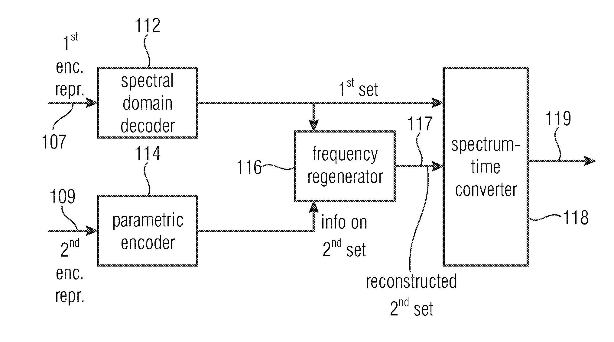
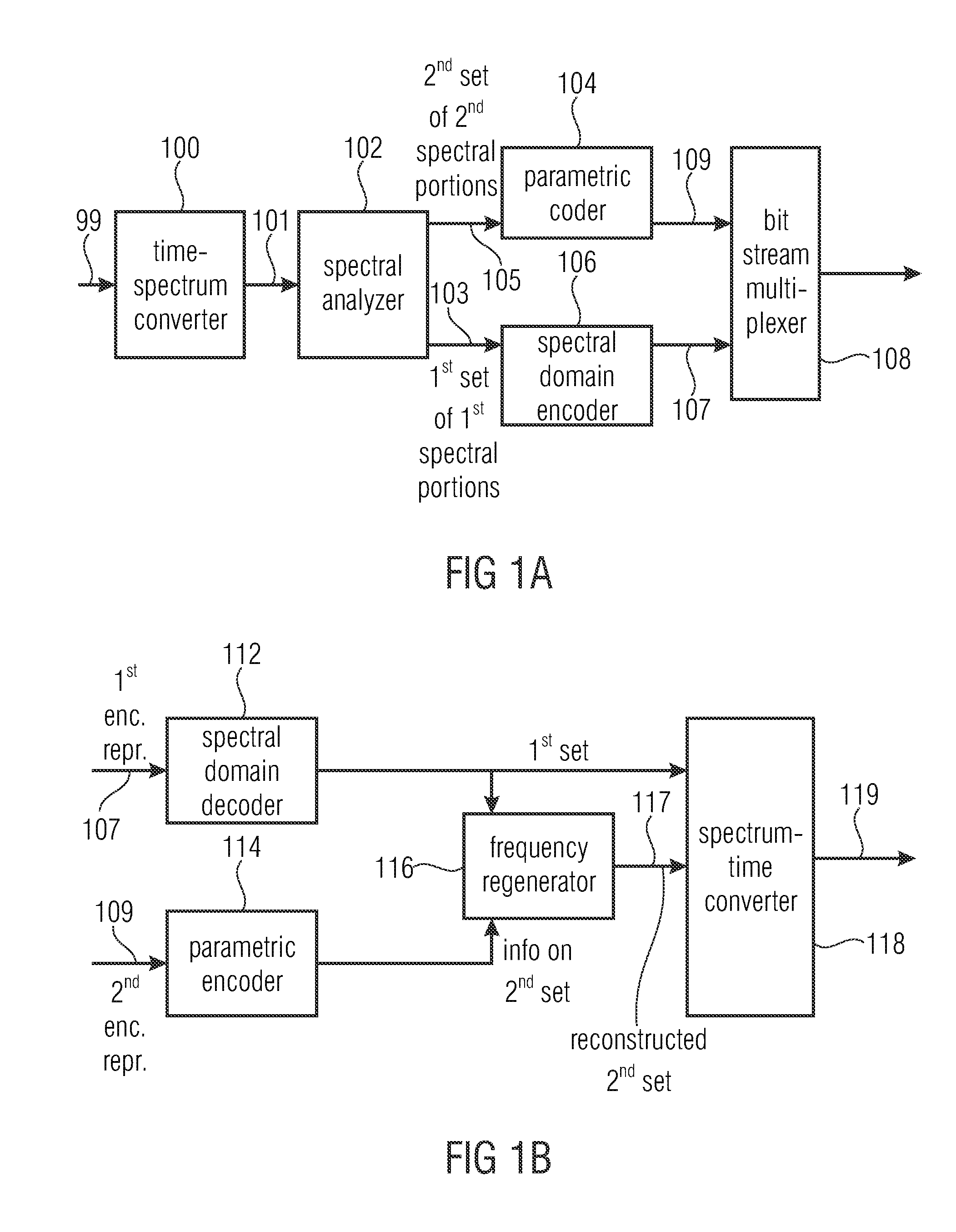
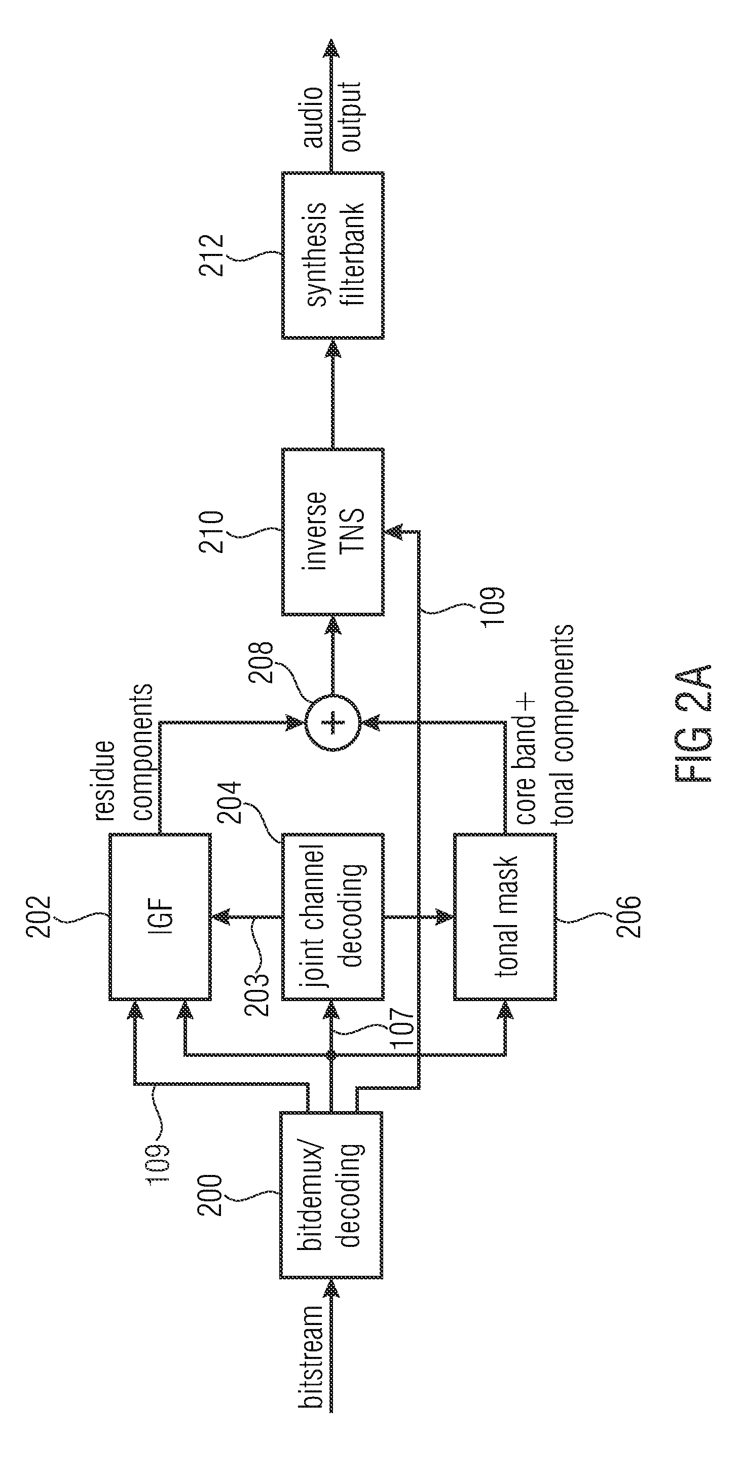
[0078]FIG. 1a illustrates an apparatus for encoding an audio signal 99. The audio signal 99 is input into a time spectrum converter 100 for converting an audio signal having a sampling rate into a spectral representation 101 output by the time spectrum converter. The spectrum 101 is input into a spectral analyzer 102 for analyzing the spectral representation 101. The spectral analyzer 101 is configured for determining a first set of first spectral portions 103 to be encoded with a first spectral resolution and a different second set of second spectral portions 105 to be encoded with a second spectral resolution. The second spectral resolution is smaller than the first spectral resolution. The second set of second spectral portions 105 is input into a parameter calculator or parametric coder 104 for calculating spectral envelope information having the second spectral resolution. Furthermore, a spectral domain audio coder 106 is provided for generating a first encoded representation 1...


PUM


Abstract

An apparatus for decoding an encoded audio signal, includes: a spectral domain audio decoder for generating a first decoded representation of a first set of first spectral portions being spectral prediction residual values; a frequency regenerator for generating a reconstructed second spectral portion using a first spectral portion of the first set of first spectral portions, wherein the reconstructed second spectral portion additionally includes spectral prediction residual values; and an inverse prediction filter for performing an inverse prediction over frequency using the spectral residual values for the first set of first spectral portions and the reconstructed second spectral portion using prediction filter information included in the encoded audio signal.

Description

CROSS-REFERENCE TO RELATED APPLICATIONS[0001]This application is a continuation of copending International Application No. PCT / EP2014 / 065123, filed Jul. 15, 2014, which is incorporated herein in its entirety by this reference thereto, and additionally claims priority from European Applications Nos. EP13177353.3, filed Jul. 22, 2013, EP13177350.9, filed Jul. 22, 2013, EP13177348.3, filed Jul. 22, 2013, EP13177346.7, filed Jul. 22, 2013, and EP13189358.8, filed Oct. 18, 2013, which are each incorporated herein in its entirety by this reference thereto.BACKGROUND OF THE INVENTION[0002]The present invention relates to audio coding / decoding and, particularly, to audio coding using Intelligent Gap Filling (IGF).[0003]Audio coding is the domain of signal compression that deals with exploiting redundancy and irrelevancy in audio signals using psychoacoustic knowledge. Today audio codecs typically need around 60 kbps / channel for perceptually transparent coding of almost any type of audio sig...

Claims


Application Information

Patent Timeline
Patent Type & Authority Applications(United States)
IPC IPC(8): G10L19/02
CPCG10L19/02G10L21/0388G10L19/025G10L19/028G10L19/03G10L21/038G10L19/008G10L19/0204G10L19/0212G10L19/022G10L19/032G10L19/06G10L19/18H03M7/30G10L19/0208H04S1/007G10L25/18G10L25/21G10L25/06
Inventor DISCH, SASCHANAGEL, FREDERIKGEIGER, RALFTHOSHKAHNA, BALAJI NAGENDRANSCHMIDT, KONSTANTINBAYER, STEFANNEUKAM, CHRISTIANEDLER, BERNDHELMRICH, CHRISTIAN
Owner FRAUNHOFER GESELLSCHAFT ZUR FOERDERUNG DER ANGEWANDTEN FORSCHUNG EV
Learn More