Method of manufacturing coil for stators mounted in rotary electric machines

Active Publication Date: 2010-01-07
DENSO CORP
View PDF4 Cites 10 Cited by
  • Summary
  • Abstract
  • Description
  • Claims
  • Application Information

AI Technical Summary

Benefits of technology

[0021]According to a seventh mode of the present invention, at the winding step, a plurality of integrated bodies are used, with the straight portions of the integrated bodies being stuck one on the other and fitted to fitting grooves of an alignment member, the fitting grooves being formed in the alignment member at intervals each corresponding to the size of a gap between adjacent ones of the plurality of straight stack portions, the integrated bodies being wound about the core member together with the alignment member, with the straight portions being fitted to the alignment member to form the wound-up body. With this configuration, the integrated body and the alignment member are conveyed by the conveyor belt, exerting an advantage of stably conveying the integrated body to the core member.
[0022]According to an eighth mode of the present invention, at the winding step, conveyor gears that engage with each other are provided at the conveyor belt and the alignment member to convey the integrated body and the alignment member by the conveyor belt, while the conveyor gears are being engaged with each other. With this configuration, when the integrated body and the alignment member are conveyed by the conveyor belt, the conveyance is performed while the conveyor gears are being engaged with each other. Therefore, the occurrence of positional offset in the conveyance direction can be prevented between the conveyor belt, and the integrated body and the alignment member. This may ensure stable conveyance and performance of winding turns.
[0023]According to a ninth mode of the present invention, at the winding step, the integrated body is wound up with rotation of the core member, while speed of advance of the conveyor belt is adjusted so that the integrated body and the alignment member can be conveyed according to speed of advance of th

Problems solved by technology

However, the above manufacturing method is likely to cause offset in the superposition of the straight portions of the straight superposed portions, or to provide uneven intervals between adjacent straight superposed portions in the integrated body.
Therefore, in an obtained wound-up body, it is likely that offset is caused in the superposition of the plurality of straight portions in the respective straight stack portions, or the intervals are uneven between adjacent straight stack portions.
Therefore, this may degrade

Method used


Image

  • Method of manufacturing coil for stators mounted in rotary electric machines
  • Method of manufacturing coil for stators mounted in rotary electric machines
  • Method of manufacturing coil for stators mounted in rotary electric machines

Examples


first embodiment

[0056]Referring to FIGS. 1 to 17, hereinafter will be described, in detail, a first embodiment of a method of manufacturing a stator coil related to the present invention.

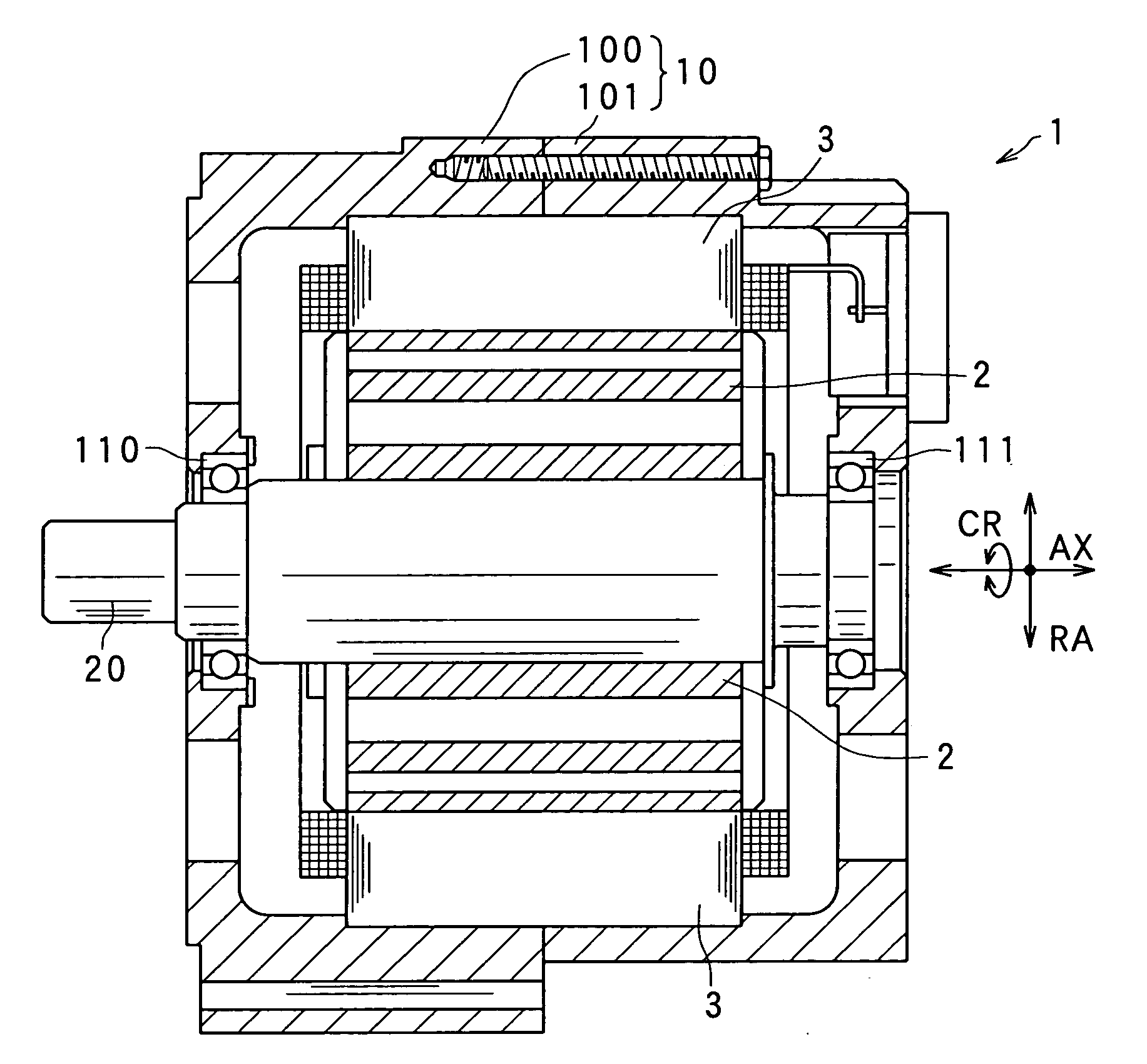
[0057]First, a configuration of a rotary electric machine 1 is described. The rotary electric machine 1 is integrated with a stator coil that has been obtained by the method of manufacturing a stator coil according to the present embodiment. The rotary electric machine 1 may, for example, be an electric motor, an electric generator or a motor generator, which is loaded on a vehicle.

[0058]As shown in FIG. 1, the rotary electric machine 1 includes: a housing 10 consisting of a pair of bottomed housing members 100, 101 each having substantially a cylindrical shape and joined to each other at the opening portions thereof; a rotary shaft 20 rotatably supported by the housing 10 via bearings 110, 111; a rotor 2 secured to the rotary shaft 20; and a stator 3 secured to the housing 10, being located at a position of enclos...

second embodiment

[0101]Referring now to FIG. 18, hereinafter will be described a second embodiment of a method of manufacturing a stator coil related to the present invention. In the present and the subsequent embodiments, the components having functions identical with or similar to those in the first embodiment described above are designated with the same references to omit or simplify the descriptions.

[0102]In the first embodiment described above, no particular processes have been performed from when the integrated body 47 has been fitted to the alignment member 500 to when the integrated body 47 is wound about the core member 600. However, the present invention is not intended to be limited to this, but may be configured differently. Specifically, as a pre-process prior to winding the integrated body 47 about the core member 600, the integrated body 47 may be subjected to round shaping (curve shaping) to cope with the curvature of the winding face 601. FIG. 18 is a side view illustrating a config...

third embodiment

[0107]Referring now to FIG. 19, hereinafter is described a third embodiment of a method of manufacturing a stator coil related to the present invention.

[0108]In the first embodiment described above, a plurality of integrated bodies have been fitted to the alignment member 500 first, and then wound about the core member 600 with a plurality of winding turns. In the third embodiment, however, the integrated body 47 is divided in advance into pieces each of which corresponds to one winding turn. The plurality of pieces of divided integrated body 47 are fitted to the alignment member 500 and then wound about the core member 600. Compared to the first embodiment, this can reduce the number of winding turns imparted to the core member 600. Further, compared to the first embodiment, the pieces of integrated body, each of which has been divided to have a length corresponding to that of each winding turn, can be located in a compact space to thereby additionally exert an advantage of reducin...


PUM

PropertyMeasurementUnit
Sizeaaaaaaaaaa
Speedaaaaaaaaaa
Electrical conductoraaaaaaaaaa

Abstract

In manufacturing a stator coil for rotary electric machine having phase windings, plural conductive shaped wire members are integrated mutually to form an integrated body. Each shaped wire member has plural straight portions, and plural turn portions alternately connecting adjacent straight portions at each of both ends of each straight portion. The body has plural straight superposed portions each formed by mutually superposing the plural straight portions. A wound-up body has plural straight stack portions. The straight portions are fitted to respective fitting grooves of an alignment member, the fitting grooves being formed in the alignment member at intervals each corresponding to the size of a gap between adjacent straight stack portions. The integrated body is wound about a core member together with the alignment member, with the straight portions being fitted to the alignment member to form the wound-up body.

Description

CROSS-REFERENCE TO RELATED APPLICATION[0001]This application is based on and claims the benefit of priority from earlier Japanese Patent Applications No. 2008-177291 filed on Jul. 7, 2008, No. 2008-210049 filed Aug. 18, 2008, and No. 2009-156914 filed Jul. 1, 2009, the description of which are incorporated herein by reference.BACKGROUND OF THE INVENTION[0002]1. Technical Field of the Invention[0003]The present invention relates to a method of manufacturing coil for stators mounted in rotary electric machines, and in particular, to a method of manufacturing coil (also referred to as a stator coil) used for stators mounted in rotary electric machines which are loaded on vehicles.[0004]2. Related Art[0005]In recent years, small size, high power and high quality have been demanded of rotary electric machines used as electric motors and electric generators. Taking rotary electric machines loaded on vehicles as an example, the space for loading such a rotary electric machine has been incr...

Claims


Application Information

Patent Timeline
IPC IPC(8): H01F7/06
CPCH02K1/148H02K1/16H02K15/024H02K15/0421Y10T29/49071H02K15/066Y10T29/49009Y10T29/49062Y10T29/49096H02K15/064
Inventor AKIMOTO, AKITOYANAGISAWA, YOSHINOBUMURAKI, SHUZODOBASHI, MASAOMIMITSUKI, KENTAROISHIZUKA, ATSUO
Owner DENSO CORP
Why Eureka
Try Eureka