Container lid having multiple utilities

a technology of container lids and utilities, applied in the field of container lids, can solve the problems and achieve the effect of prolonging the life of the final cleaning apparatus and maintaining the original consistency of the material

Inactive Publication Date: 2010-01-07
YARBROUGH GLEN A
View PDF0 Cites 17 Cited by
  • Summary
  • Abstract
  • Description
  • Claims
  • Application Information

AI Technical Summary

Benefits of technology

[0012]In another alternative, a flexible air-tight bag is fitted into an inlet port and secured in place. With the use of a built-in, hand-operated air pump, air in container is forced out and ambient air is drawn into the bag. The air expands the bag, forcing the bag to assume the contour of the paste-like material, thus keeping air from contacting the paste-like material and the original consistency of the material is maintained. With repeated pumping, the pressure of the air within the container may made to be lower than ambient pressure so that the “amount” (P×V) of air available to react with the material is less than that which would be available had the bladder been filled using high pressure.
[0013]The second embodiment of the present invention discloses a device for pre-cleaning air ...

Problems solved by technology

By use of the above device, the air coming from the source of dirty air is...

Method used


Image

  • Container lid having multiple utilities
  • Container lid having multiple utilities
  • Container lid having multiple utilities

Examples


first embodiment

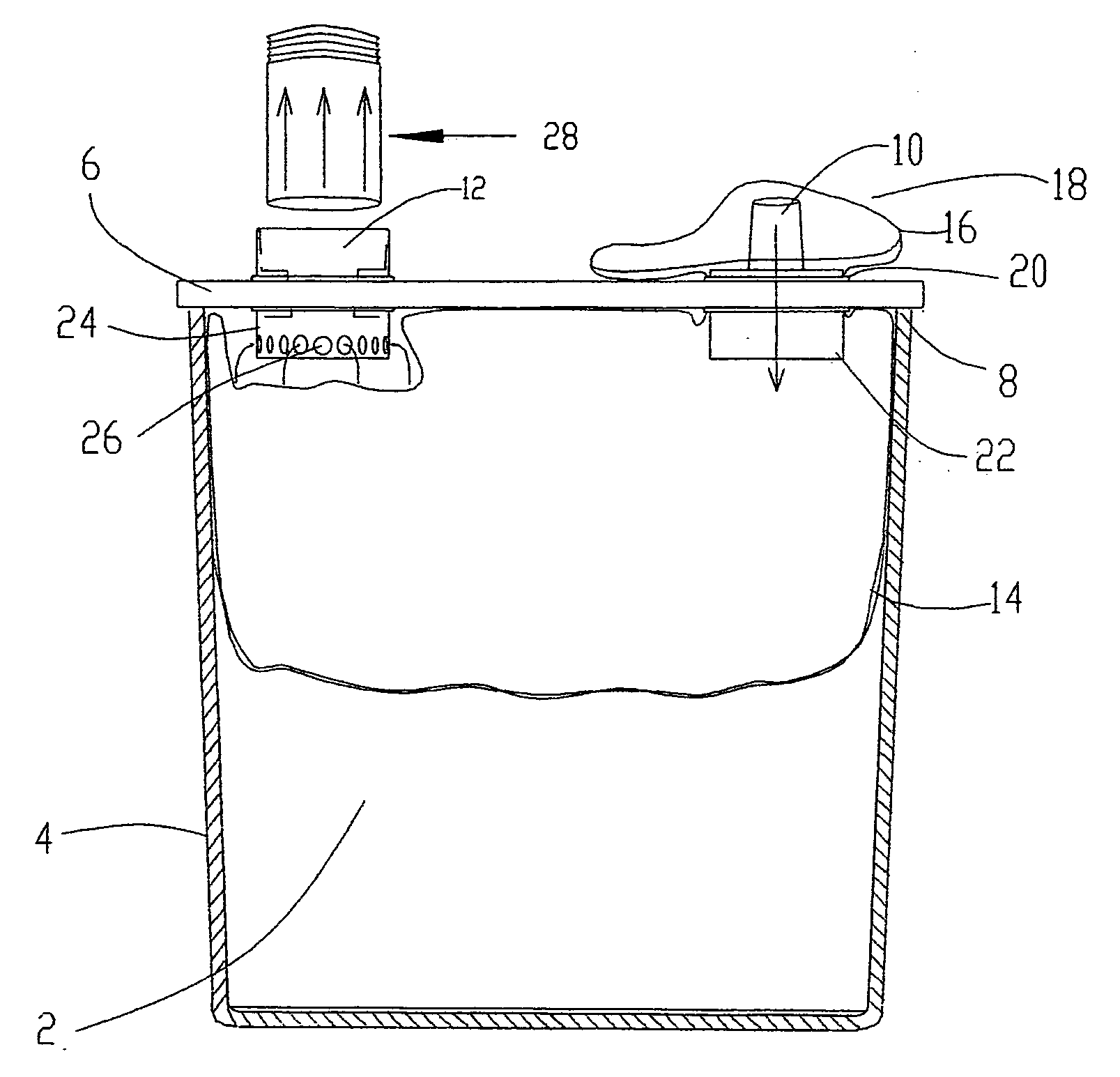
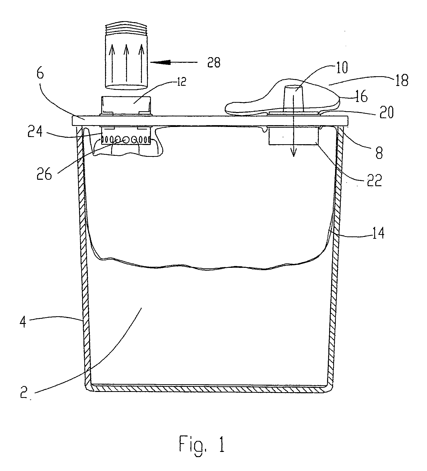
[0020]this invention is directed to keeping paste-like materials or liquids 2 in containers 4 such as pails or cans in a fresh condition during storage. Such material 2 is basically any material that is stored in the container 4 and has a tendency to dry out due to contact with air during storage. The container 4 is made of metal or plastic and is of conventional size of containers used in the art, such as one gallon or five gallon cans or pails. To accomplish this goal the invention uses a pre-sized lid 6, usually of plastic, which snaps onto the top edge 8 of the container 4.

[0021]In a first alternative of the first embodiment, shown in FIG. 1, the lid 6 for a container 4 has an inlet port 10 and an outlet port 12. A strong, flexible bag 14, conveniently a plastic bag, is fit through a first, inlet, port 10 so that the mouth 16 of the bag 14 will be toward the outside 18 of the container 4 when the lid 6 and the container 4 are joined. The bag 14 and the port 10 may be securely fa...

second embodiment

[0024]this invention is described with reference to FIG. 3. This embodiment provides a device 34 for pre-filtering dirty air before it comes in contact with the conventional filter within a wet / dry vacuum device (not shown). The device 34 of this invention provides longer useful operation time of the wet / dry vacuum device without clogging the filter medium. This device 34 has a container 36 such as a pail and a lid 38. The device 34 is based on the function of forcing dirty air into water 40 that is placed in the bottom 42 of the device 34. A conventional wet / dry vacuum attached to the device 34 by an outlet tube 44 is used to create a vacuum which is used to bring the dirty air into the container 36 by way of an intake tube 46. The origin of the dirty air may be an industrial tool 48 such as a sander or circular saw. The tool 48 is connected by means of an intake tube 46 having an appropriate inlet fitting 50 to the inlet port 52 of the pre-cleaning device 34. An inlet tube 5...

third embodiment

[0026]the present invention will be described with reference to FIGS. 4 and 5. The third embodiment is a hand sander 64 of such construction as to provide a quick and efficient way to replace the sandpaper 66. A disengagement button 68 at the top 70 of the handle component 72 is operatively connected with a hook-like latch 74 which engages and disengages the handle component 72 and the bottom surface component 76 of the sander 64. Upon depression of the button 68, the bottom surface component 76 of the sander 64 is disengaged and swings open about a pivot point 78 at the rear of the sander 64. Alternatively, the sander 64 may be configured with a removable bottom surface component 76 that may be attached to the handle component 72 with any form of fastener. In either alternative, the bottom surface component 76 is constructed with horizontal slots 80 at both ends 82, 84. These slots 80 are for the purpose of accepting and holding the ends 86 of the sandpaper 66. As the bottom surfac...


PUM


Abstract

The prevention from hardening upon storage of paste-like material by use of a lid having an inlet port, an outlet port, and a plastic bag attached to the inlet port. By expelling the air in contact with the paste-like material, the material can be prevented from hardening during storage. A similar lid is used in a pre-cleaning device situated between a dust-producing tool and a wet/dry vacuum. Dust-laden air enters the device through an inlet port and is discharged over a water filter. The pre-cleaned air is vacuumed to a wet/dry vacuum. The pre-cleaning process lengthens the useful life of the wet/dry vacuum. A hand-held sander is disclosed which provides for rapid change of sandpaper. The sander has a hollow upper handle component and a lower surface component which are held together with a latch. Depressing of a quick-release button allows separation of the two parts.

Description

CROSS-REFERENCE TO RELATED APPLICATIONS[0001]This application claims the filing date of applicant's provisional application, Ser. No. 60 / 999,779, having an effective filing date of Jul. 1, 2008, which is incorporated herein by reference.STATEMENT REGARDING FEDERALLY SPONSORED RESEARCH OR DEVELOPMENT[0002](Not applicable)REFERENCE TO SEQUENTIAL LISTING, A TABLE, OR A COMPUTER PROGRAM LISTING APPENDIX SUBMITTED ON A COMPACT DISC[0003](Not applicable)BACKGROUND OF THE INVENTION[0004]1) Field of the Invention[0005]This invention is directed to container lids which have multiple utilities and to processes for using these lids. One disclosed utility is keeping paste-like and liquid compositions from becoming hard during storage. Another disclosed utility is pre-cleaning air from an industrial tool prior to entrance into a wet / dry vacuum cleaner. This invention is also directed to a hand-held sander which has a fast and simple release of the sandpaper which may be used in combination with ...

Claims


Application Information

Patent Timeline
IPC IPC(8): B65D51/24
CPCB65D25/16A47L9/182
Inventor YARBROUGH, GLEN A.
Owner YARBROUGH GLEN A
Why Eureka
Try Eureka