High-speed aircraft with vertical lift and self-revolving ability

a high-speed aircraft and vertical lift technology, applied in the field of aircraft, can solve the problems of low-speed, low-speed, and no escaping equipment, and achieve the effect of high safety design

Inactive Publication Date: 2010-01-07
SUN WEI HONG
View PDF36 Cites 43 Cited by
  • Summary
  • Abstract
  • Description
  • Claims
  • Application Information

AI Technical Summary

Benefits of technology

[0006]In view of the limitations in terms of the safety issues of the conventional helicopter and the conventional autogyro, the preferred embodiment provides a new kind of aircraft with the function of vertical maneuvering capability independent to terrain, and gliding ability under mechanical failure.
[0015]The aircraft in the preferred embodiment is provided with both the coaxial rotor assembly and the rear propeller, drivable by its own motor respectively. Therefore, when there is a mechanical failure responsible for driving the coaxial rotor assembly, the rear propeller can provide the aircraft with a horizontal thrust to move the aircraft forward continually. In the same time, the rotating rotor is shifted from active rotation into inertial rotation and then into self-rotation, so as to provide the vertical thrust together with the fixed wings mounted on the opposite sides of the fuselage of the aircraft, to proceed with the flight. When there is a breakdown in the motor responsible for the rear propeller, the coaxial rotor assembly can provide both horizontal thrust and vertical thrust to proceed forward in the mode of the conventional helicopter. Since there will be no danger when one motor fails to work, the whole safety of the aircraft is improved.
[0018]Due to the regulator of the coaxial rotor assembly, the angle of the rotational surface of rotor relative to the ground can be adjustable. If necessary, the aircraft can fly in the mode of autogyro. The rear propeller driven by the second motor provides the aircraft with the horizontal thrust, while the coaxial rotor assembly can be tilted backward to form a positive angle of the rotational surface of rotor relative to the ground and self-rotates to provide the aircraft with a vertical thrust during flight. Of course, the aircraft can fly in high-speed mode. In the meantime, the coaxial rotor assembly can also be tilted forward to form a little negative angle of the rotational surface of rotor relative to the ground. Under the effect of airflow, a horizontal component provides a forward power in combination with the power of the rear propeller, so flight of higher-speed is achieved. If the two motors do work, the larger the negative angle of the rotational surface of rotor relative to the ground is, the larger forward thrust the aircraft has, so the aircraft can fly at a very high-speed. Therefore, the aircraft of the preferred embodiment has advantages of both helicopter and autogyro, such as high safety design, high-speed, no limitation of terrain etc.

Problems solved by technology

While the rotor is providing the lift, an undesired torque is simultaneously created to cause the fuselage to revolve in a direction counter to the direction of rotor blade assembly.
Such a helicopter design associates with a lot of disadvantages such as structural complexity, low-speed, no escaping equipment and no gliding function.
When there are some mechanical failures in the rotor blade assembly or the motor assembly, the crewmembers are difficult to escape, so the flight safety measures of such design is insufficient.
However, the autogyro can not take off and land vertically, and hover in the air like the conventional helicopter.
The conventional autogyro has some restrictions to terrain and can not achieve some specific flight task requirements.

Method used


Image

  • High-speed aircraft with vertical lift and self-revolving ability
  • High-speed aircraft with vertical lift and self-revolving ability
  • High-speed aircraft with vertical lift and self-revolving ability

Examples


Embodiment Construction

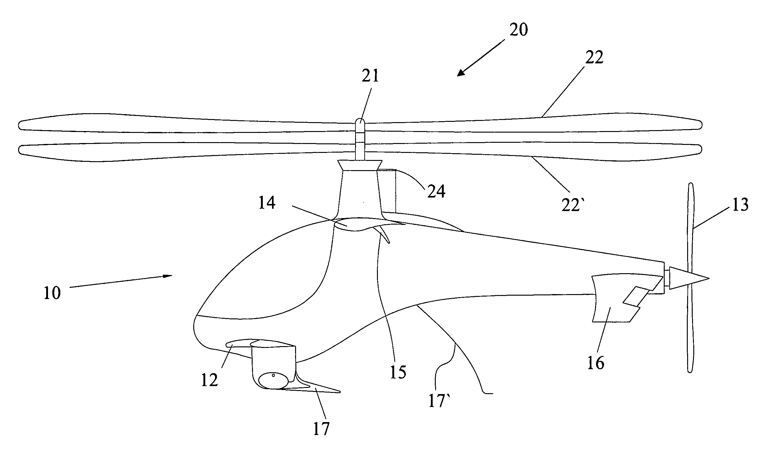
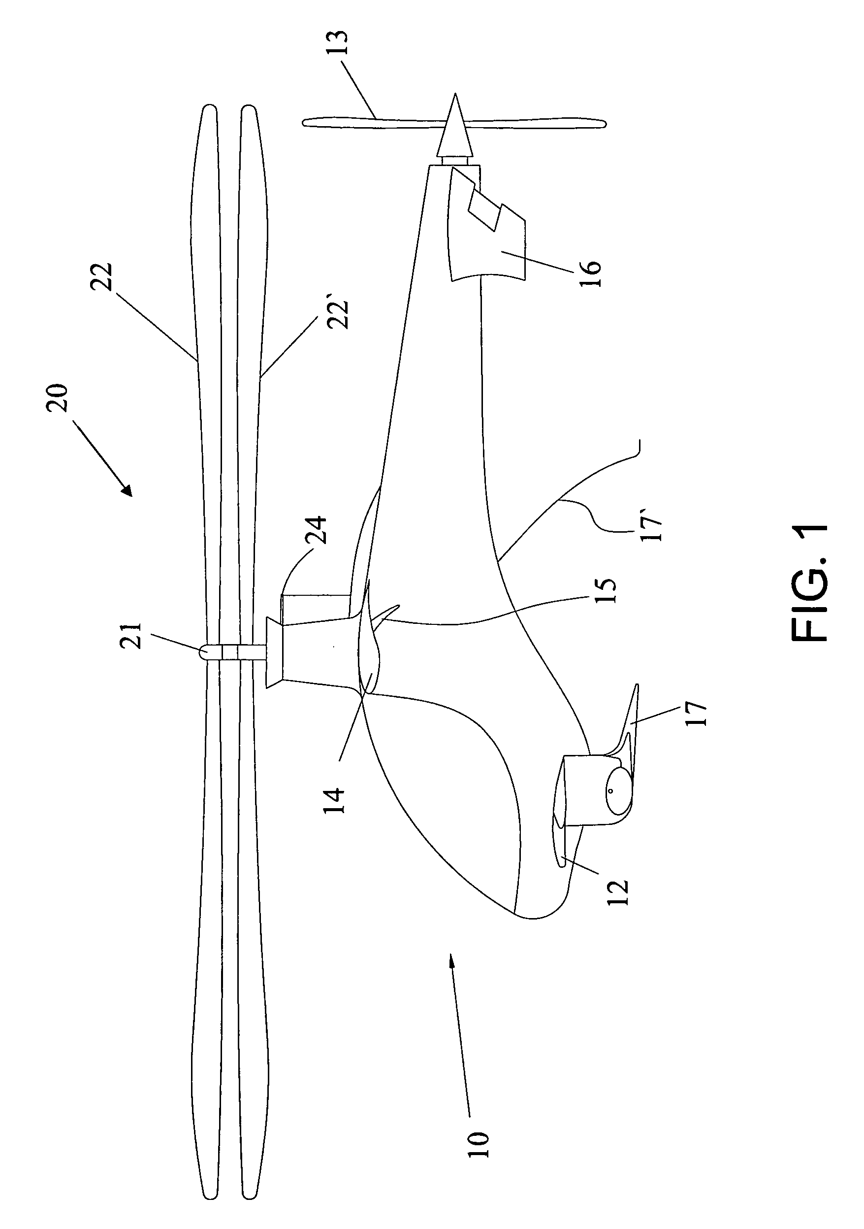
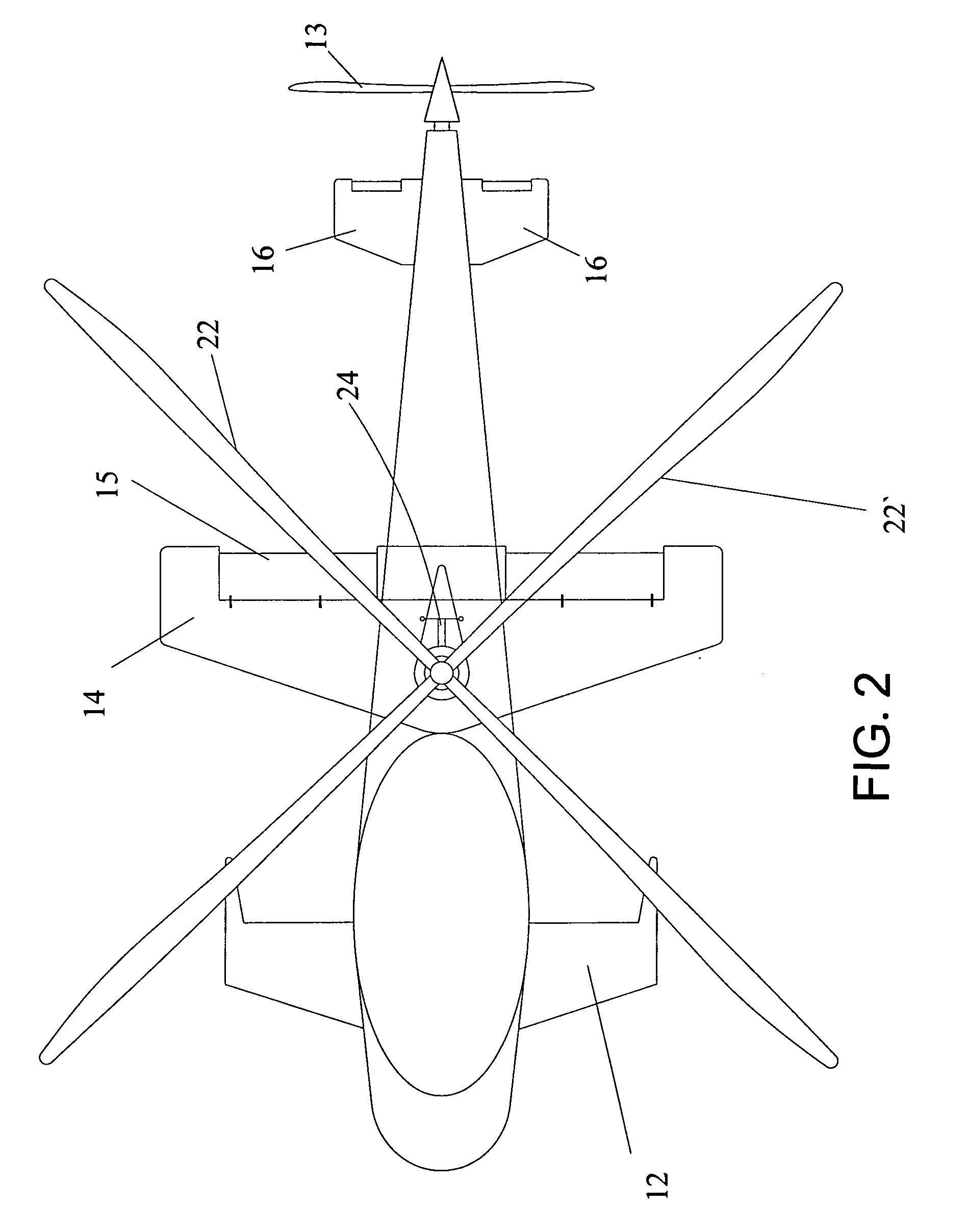
[0030]As shown in FIGS. 1 to 3, a front and top view of the aircraft of the preferred embodiment respectively, the aircraft with the functions of vertical lift and self-revolving according to the preferred embodiment comprises:

[0031]a fuselage 10, containing a first motor 11 and a second motor 18 therein;

[0032]a cockpit 19 formed in the fuselage 10;

[0033]a coaxial rotor assembly 20 mounted on the top of the fuselage 10, wherein the coaxial rotor assembly 20 contains an upper rotor 22 and a lower rotor 22′, installed on a rotor shaft 21 over the fuselage 10 successively. Preferably, the upper rotor 22 and the lower rotor 22′ may have fixed pitch rotor blade. The upper rotor 22 and the lower rotor 22′ may be driven by a first motor 11 inside the fuselage 10. Concretely, as shown in FIG. 4A, the first motor 11 is connected with a belt pulley 25, then to a reduction belt pulley 26 and finally to the rotor shaft 21, to drive the rotor shaft 21. By the rotor shaft 21, the upper rotor 22 a...


PUM


Abstract

An aircraft includes a fuselage; a cockpit formed in the fuselage; a coaxial rotor assembly mounted to the top of fuselage, containing an upper rotor and a lower rotor, drivable by a first motor inside the fuselage; wherein, the aircraft also comprises: a couple of fixed wings mounted to the opposite sides of the aircraft respectively; and a rear propeller mounted to the tail end of fuselage, driven by a second motor inside the fuselage. The aircraft of the invention has the advantages of helicopter and autogyro, such as high-safety and high-speed.

Description

BACKGROUND OF THE INVENTION[0001]1. Field of the Invention[0002]The present invention relates to an aircraft, especially to an aircraft with functions of a helicopter and an autogyro.[0003]2. Description of the Prior Art[0004]A helicopter is almost used in every civil and military field because it can ascend or descend vertically, hover in midair, and travel in any direction such as forward, backward, or sideways. A helicopter is one of rotorcrafts. It is provided with one or more rotors, and each of which is similar to a long propeller. The rotor blade assembly is mounted on a nearly perpendicular rotor shaft over the fuselage and driven by a motor to revolve so as to provide a lifting force, thus the helicopter can ascend or descend vertically. Controlled by a swash plate, the rotor disc can be tilted forward relative to the ground for an angle, such as 6˜15°, so that the direction of the lifting force is changed to provide the helicopter with a horizontal thrust for powering the ...

Claims


Application Information

Patent Timeline
Patent Type & Authority Applications(United States)
IPC IPC(8): B64C27/26B64C27/08B64C5/04B64C25/02B64C1/00B64C27/52
CPCB64C27/025B64C27/10B64C2027/8236B64C27/52B64C27/26
Inventor SUN, WEI HONG
Owner SUN WEI HONG
Why Eureka
Try Eureka