
Output voltage control circuit for modular power supplies

a technology of output voltage control and power supply, which is applied in the direction of power conversion systems, dc-dc conversion, instruments, etc., can solve the problems of low cost, accuracy and drift problems, and the connection between these electrical contacts becomes less and less reliable. , to achieve the effect of low cost and convenient operation or implementation

Inactive Publication Date: 2010-01-07
MURATA POWER SOLUTIONS
View PDF39 Cites 25 Cited by
  • Summary
  • Abstract
  • Description
  • Claims
  • Application Information

AI Technical Summary

Benefits of technology

[0010]To overcome the problems described above, preferred embodiments of the present invention provide methods and circuits for adjusting a voltage output of a modular power converter that are reliable, low cost, and easy to perform or implement.

Problems solved by technology

If the wrong output voltage is applied to a load, there is a risk of the load not functioning properly or being damaged or destroyed.
Over time, the connection between these electrical contacts becomes less and less reliable due to wear on the electrical contacts.
Second, using a single turn potentiometer usually results in accuracy and drift problems.
However, multi-turn potentiometers are too expensive to justify using them in all applications.
However, digital potentiometers can only be adjusted through some type of software interface like I2C (IC to IC) or SPI (Serial Peripheral Interface, also known as Microwire) connected to a computer.
Accordingly, it is not easy to change the resistance of digital potentiometers as with mechanical potentiometers.
This adjustment method is very mechanically complicated and thus is not desirable in applications where the output of the power converter is adjusted frequently.
However, this method requires a plurality of digital inputs to be supplied to the power supplies to change the output voltage of the power converter.
The connections between the digital inputs and the individual power modules can be difficult and complicated, and it is not convenient to change the output level of an individual power module on the fly with this method.

Method used


Image

  • Output voltage control circuit for modular power supplies
  • Output voltage control circuit for modular power supplies
  • Output voltage control circuit for modular power supplies

Examples


Embodiment Construction

[0032]The preferred embodiments of the present invention are discussed below with respect to the figures. These preferred embodiments provide output voltage control methods and circuits that have high set point accuracy with minimal voltage drift. These preferred embodiments provide output voltage control methods and circuits that can be used for both manual adjustments and automatic adjustments that are performed, for example, during factory calibration.

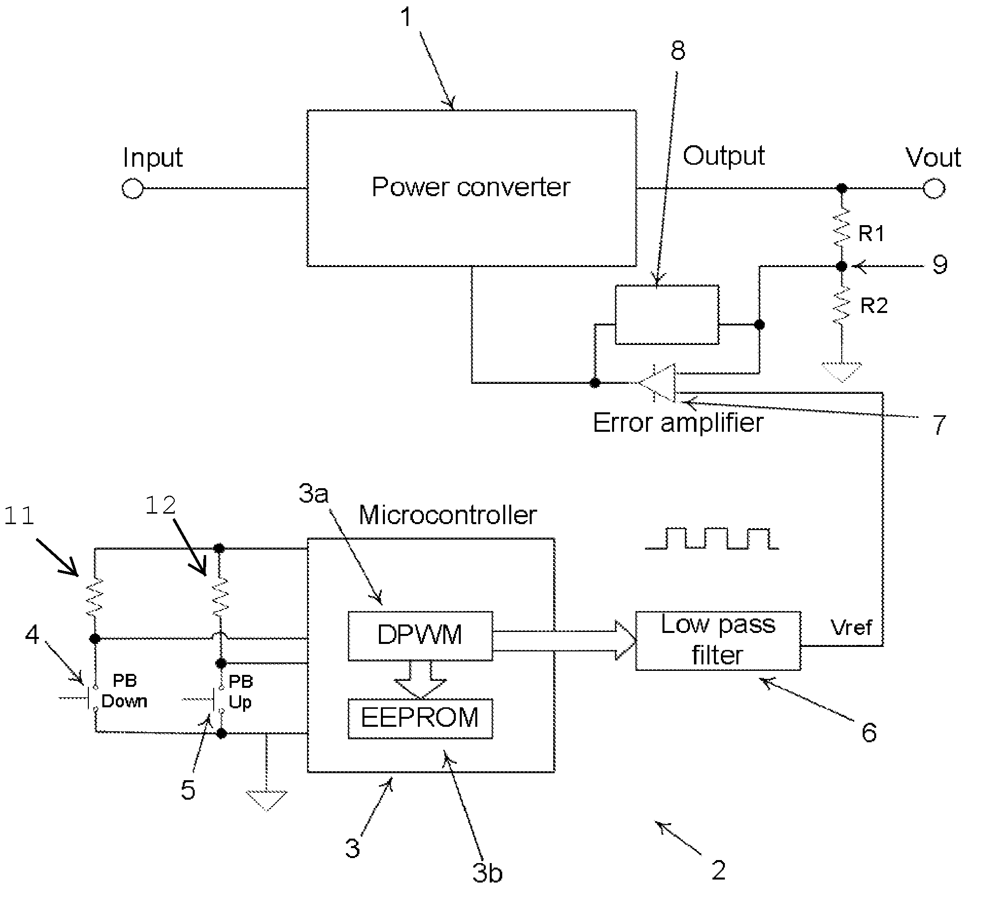
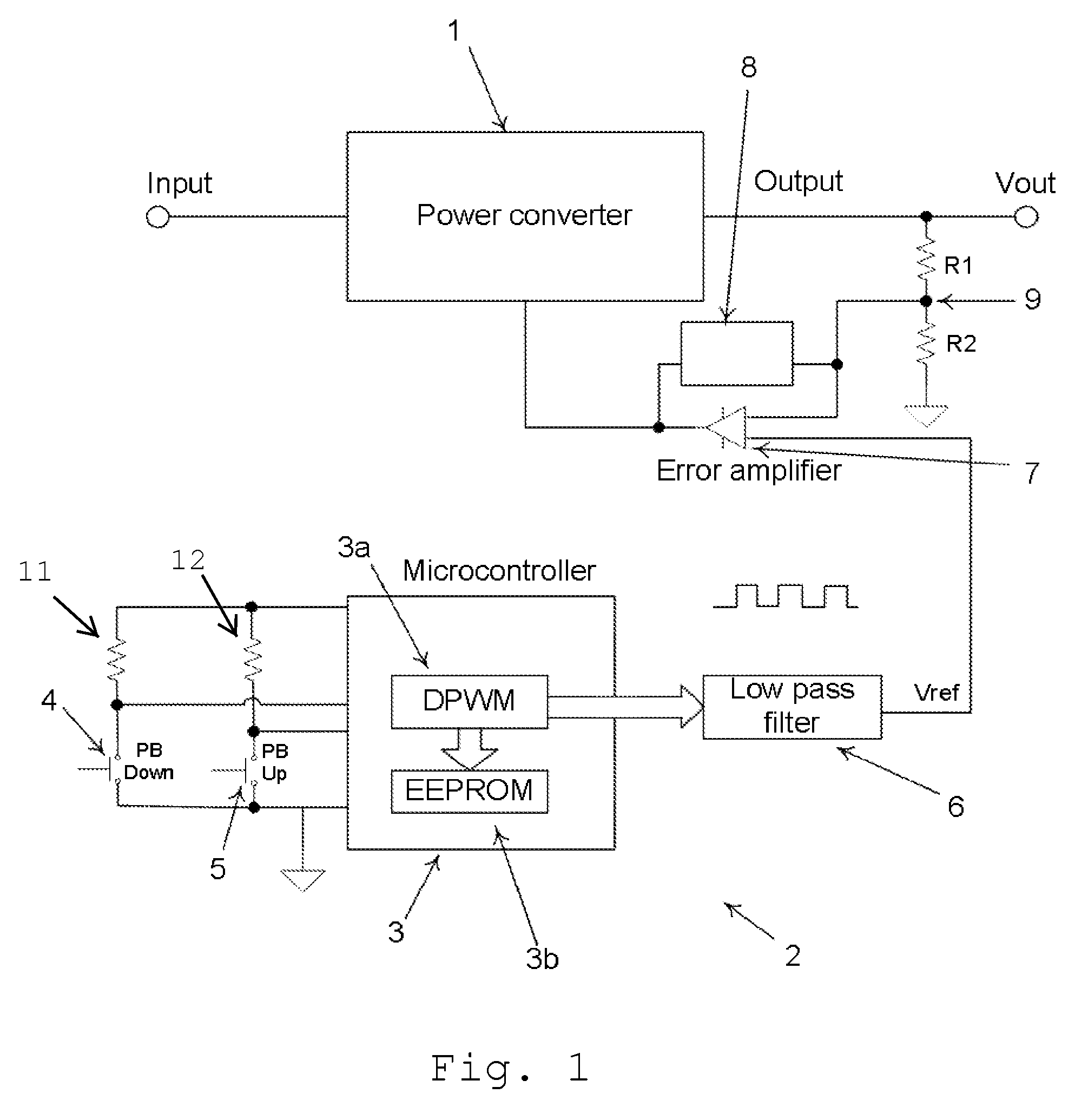
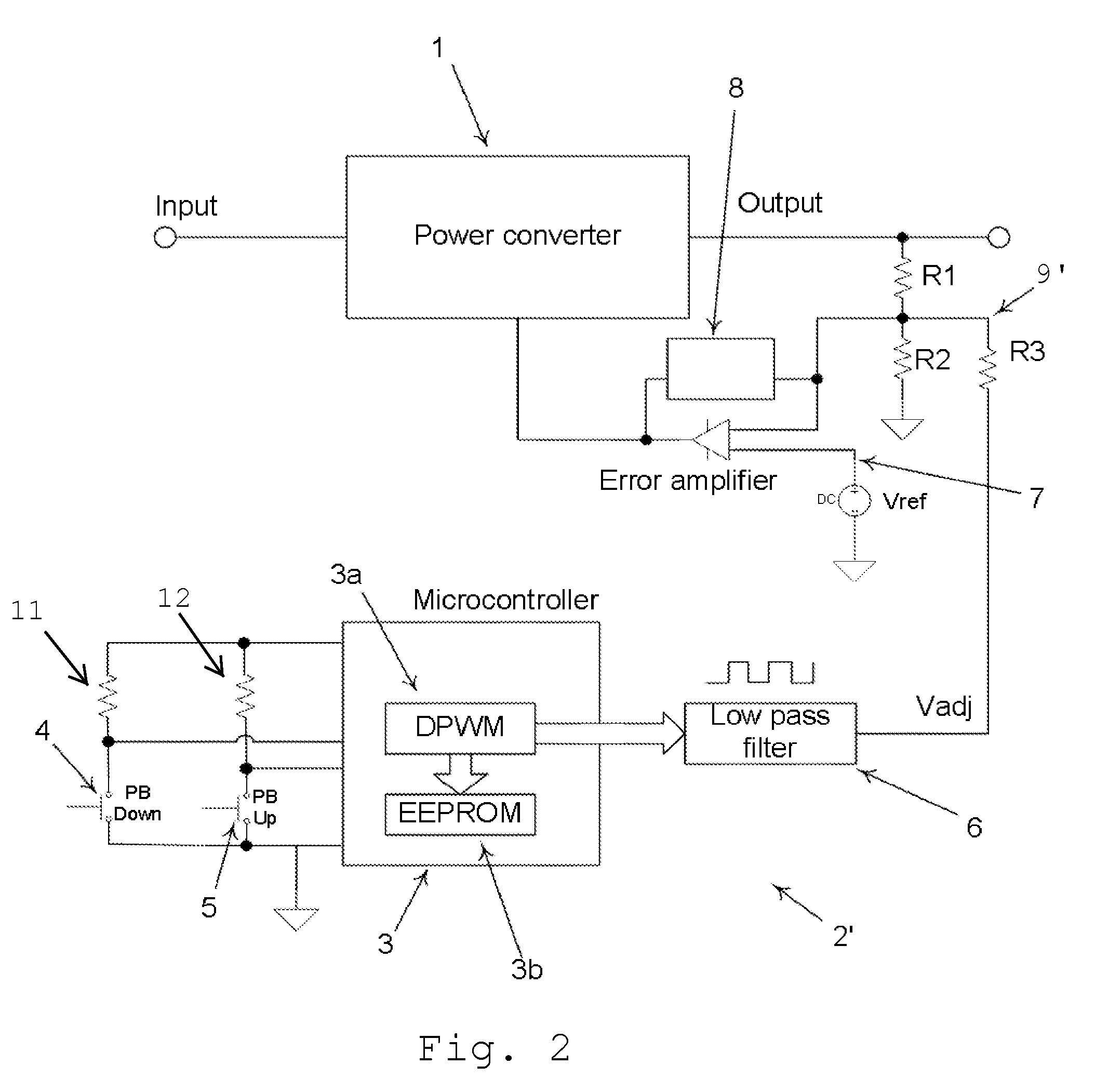
[0033]FIG. 1 shows a circuit diagram of the control system according to a first preferred embodiment of the present invention. The control system according to the first preferred embodiment of the present invention includes a control circuit 2 connected to a modular power converter 1. The power converter 1 receives an input and a control signal and provides an output voltage. The control signal controls the voltage level of the output voltage. While FIG. 1 only shows one power converter 1, an array of power converters 1 could also b...


PUM


Abstract

A method for adjusting an output voltage of a module includes providing a digital reference voltage, converting the digital reference voltage to an analog reference voltage, comparing the output voltage and the analog reference voltage, controlling the module based upon a result of the step of comparing the output voltage and the analog reference voltage such that the output voltage corresponds to the analog reference voltage, and adjusting the digital reference voltage. An increase in the digital reference voltage causes a corresponding increase in the output voltage, and a decrease in the digital reference voltage causes a corresponding decrease in the output voltage.

Description

BACKGROUND OF THE INVENTION[0001]1. Field of the Invention[0002]The present invention relates to modular power supplies. More specifically, the present invention relates to methods and circuits for adjusting a voltage output of a modular power converter.[0003]2. Description of the Related Art[0004]It is known in the field of modular power supplies that it is desirable to adjust the output voltage of a power converter module to ensure that a proper output voltage is provided by the modular power converter. If the wrong output voltage is applied to a load, there is a risk of the load not functioning properly or being damaged or destroyed.[0005]A first known method of adjusting the output voltage of a power converter uses a mechanical potentiometer in a voltage divider connected to the output voltage. The divided voltage is compared to a reference voltage. The potentiometer can be adjusted to change a voltage level of the divided voltage. By adjusting the voltage level of the divided v...

Claims


Application Information

Patent Timeline
Patent Type & Authority Applications(United States)
IPC IPC(8): G05F1/10
CPCH02M3/157H02M3/156
Inventor DRAGOJEVIC, MILAN
Owner MURATA POWER SOLUTIONS
Learn More