Apparatus and Method for Compressive Sensing Radar Imaging

a compressive sensing and radar imaging technology, applied in the field of radar systems, can solve the problems of imposing limitations on the resolution of radar systems, short duration pulses are very difficult to implement,

Active Publication Date: 2010-01-07
RICE UNIV
View PDF7 Cites 139 Cited by
  • Summary
  • Abstract
  • Description
  • Claims
  • Application Information

AI Technical Summary

Problems solved by technology

However, short duration pulses are very difficult to implement due to their high power, and therefore another method, known as pulse compression, is used.
Thus, currently available A/D co

Method used


Image

  • Apparatus and Method for Compressive Sensing Radar Imaging
  • Apparatus and Method for Compressive Sensing Radar Imaging
  • Apparatus and Method for Compressive Sensing Radar Imaging

Examples


example 1

Range Profile Acquisition

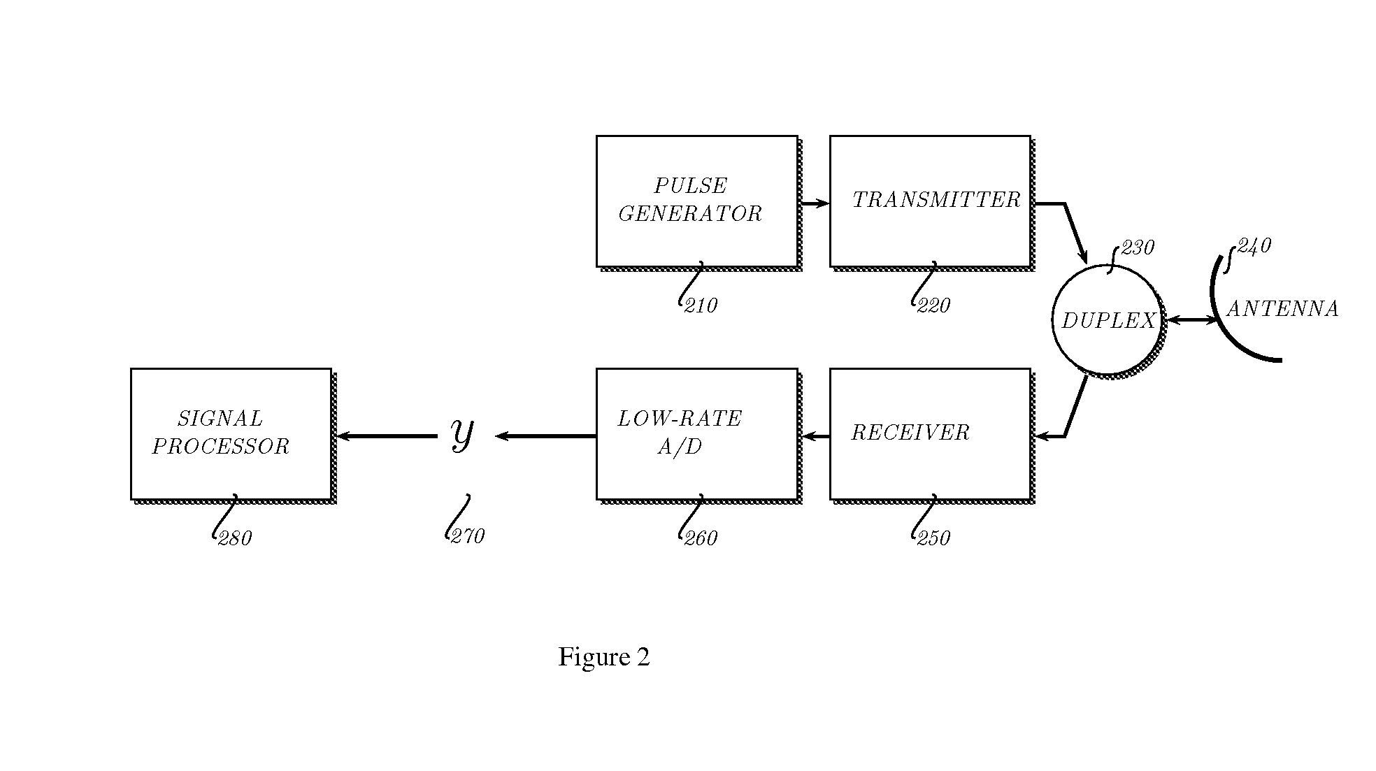
[0056]In a first example we illustrate our method with a simulation of radar range profile acquisition. A radar reflectivity profile 310 is shown in FIG. 3a. The reflectivity profile consists of a blocky background signal and a few strong point scatterers. We convolve this reflectivity sequence with a transmitted radar PN wave sequence sT(t) 320 and obtain a received wave sequence y 330 (see FIG. 2, 270). Following the analysis of the radar reflection process that was given above, this signal interacts with the target reflectivity in the form of a convolution; thus the signal arriving at the receive antenna is of the form sR(t)=sT(t)*u(t) (this is the same as a classical radar system; we use “*” to denote convolution). Now we observe that if we eliminate the matched filter (convolution with sT(t)) after the receive antenna, then we can regard the non-matched-filtered received signal sR(t) sT(t)*u(t) as a “random filtered” version of the desired signal u(t). ...

example 2

Synthetic Aperture Radar Image Acquisition

[0059]FIG. 5a shows a 2-D radar reflectivity profile 510 that we for our simple simulation of a Synthetic Aperture Radar (SAR) scene acquisition. The SAR data acquisition was simulated using a forward model for the SAR imaging process, that is described in M. Cetin, “Feature-Enhanced Synthetic Aperture Radar Imaging”, PhD Thesis, Boston University, College of Engineering, 2001. FIG. 5b shows the measurement matrix Φ520 consisting of M=N / 2 rows with the transmitted PN wave sequence. The Compressive Sensing recovery of the SAR scene 530 with two times undersampling is exact. An OMP algorithm using a combination of a time-sparse (identity) and Haar wavelet basis as the sparsity basis Ψ was used for the recovery of the SAR scene. The traditional SAR image 540 of FIG. 5d shows artifacts of the limited aperture of the imaging operator, which are absent in the image that was obtained with Compressive Sensing techniques. The result shown here is sim...


PUM


Abstract

Method and apparatus for developing radar scene and target profiles based on Compressive Sensing concept. An outgoing radar waveform is transmitted in the direction of a radar target and the radar reflectivity profile is recovered from the received radar wave sequence using a compressible or sparse representation of the radar reflectivity profile in combination with knowledge of the outgoing wave form. In an exemplary embodiment the outgoing waveform is a pseudo noise sequence or a linear FM waveform.

Description

CROSS-REFERENCE TO RELATED APPLICATIONS[0001]The present application claims the benefit of the filing date of U.S. Provisional Application Ser. No. 60 / 791,323 Att'y Docket No. 5042.011P, entitled “Compressive Sensing for Radar” and filed on Apr. 12, 2006 by inventors Richard G. Baraniuk and Phillipe Steeghs.[0002]The above cross-referenced related application is hereby incorporated by reference herein in its entirety.STATEMENT REGARDING FEDERALLY SPONSORED RESEARCH OR DEVELOPMENT[0003]The present invention was developed with funding under the following grants: NSF CCF-0431150; ONR N00014-06-1-0769; and DARPA N66001-06-1-2011.BACKGROUND OF THE INVENTION[0004]1. Field of the Invention[0005]The invention relates to radar systems and more particularly to development of high resolution radar scene profiles (i) using a lower rate sampling of a radar wave sequence than previous techniques and (ii) eliminating the pulse compression (matched filtering) as a separate signal processing step in...

Claims


Application Information

Patent Timeline
IPC IPC(8): G01S13/90
CPCG01S7/295G01S7/32G01S2013/9064G01S13/9035G01S7/411G01S13/904G01S13/9064
Inventor BARANIUK, RICHARD G.STEEGHS, THEO P.H.
Owner RICE UNIV
Why Eureka
Try Eureka