Image input/output device and method of correcting photo-reception level in image input/output device, and method of inputting image

a technology of image input/output device and image input/output device, which is applied in the direction of instruments, computing, electric digital data processing, etc., can solve the problems of inability to accurately detect adjacent objects, inconvenient binarization, and inconvenient operation of binarization, etc., and achieve high accuracy and high accuracy

Inactive Publication Date: 2010-01-07
JAPAN DISPLAY WEST
View PDF9 Cites 11 Cited by
  • Summary
  • Abstract
  • Description
  • Claims
  • Application Information

AI Technical Summary

Benefits of technology

[0012]In the method of inputting the images according to the embodiment of the present invention, correction is performed to the photo-reception signal from each of the photo-reception elements with use of correction coefficients having a value distribution profile in the display plane, the value distribution profile being defined as an inversion of a synthesized distribution profile which is a synthesis of a light intensity distribution profile in the display plane of the lights emitted from the display plane and a photo-reception sensitivity distribution profile in the display plane of the photo-reception elements. As a result, the influence from the light intensity distribution profile in the display plane of the emitted light and the photo-reception sensitivity distribution profile of the photo-reception elements is eliminated from the photo-reception signal.
[0013]In the image input / output device according to the embodiment of the present invention, photo-reception signals from the photo-reception elements are corrected with use of an in-plane correction table where correction coefficients are associated with positions on the display plane, respectively, a value distribution profile in the display plane of the correction coefficients being defined based on both of a light intensity distribution profile in the display plane of the light emitted from the display plane and a photo-reception sensitivity distribution profile in the display plane of the photo-reception elements, and information concerning one or more of position, shape and size of the external adjacent object is obtained based on the photo-reception signals corrected by the correction section. Thus, by appropriately setting the correction coefficient, it is possible to perform a suitable correction to the photo-reception signal corresponding to the light intensity distribution profile and the photo-reception sensitivity distribution profile in the display plane. In particular, in the case where the value distribution profile of the correction coefficient is defined as an inversion of a synthesized distribution profile which is a synthesis of the light intensity distribution profile and the photo-reception sensitivity distribution profile, and the correction section corrects the photo-reception signals from the photo-reception elements through multiplying the photo-reception signals by the correction coefficients, respectively, it is possible to obtain the photo-reception signal with a uniform level in which influence from the light intensity distribution profile in the display plane of the emitted light and the photo-reception sensitivity distribution profile in the display plane of the photo-reception elements is canceled. Therefore, it is possible to detect the adjacent object such as a finger with high accuracy.
[0014]In the method of inputting the images according to the embodiment of the present invention, correction is performed to the photo-reception signal from each of the photo-reception elements with use of correction coefficients having a value distribution profile in the display plane, the value distribution profile being defined as an inversion of a synthesized distribution profile which is a synthesis of a light intensity distribution profile in the display plane of the lights emitted from the display plane and a photo-reception sensitivity distribution profile in the display plane of the photo-reception elements. As a result, it is possible to obtain the photo-reception signal with a uniform level in which influence from the light intensity distribution profile in the display plane of the emitted light and the photo-reception sensitivity distribution profile in the display plane of the photo-reception elements is canceled. Therefore, it is possible to detect the adjacent object such as a finger with high accuracy.

Problems solved by technology

However, light intensity of the backlight is not uniform in a display plane in many cases (for example, a central part of the display plane has light intensity higher than that of a surrounding part).
Under this situation, when an image pickup signal is binarized to determine a position of the adjacent object, binarization may be inappropriately performed due to error of the image pickup signal which is caused by ununiformity in the light intensity of the backlight and variation of the photo-reception sensitivity of each photo-reception element.
As a result, there is a risk that the adjacent object is not accurately detected, and position detection error occurs.
That is, in the image display device including the optical type touch panel of the related art, it is difficult to detect a finger or the like with high accuracy.

Method used


Image

  • Image input/output device and method of correcting photo-reception level in image input/output device, and method of inputting image
  • Image input/output device and method of correcting photo-reception level in image input/output device, and method of inputting image
  • Image input/output device and method of correcting photo-reception level in image input/output device, and method of inputting image

Examples


modification 1

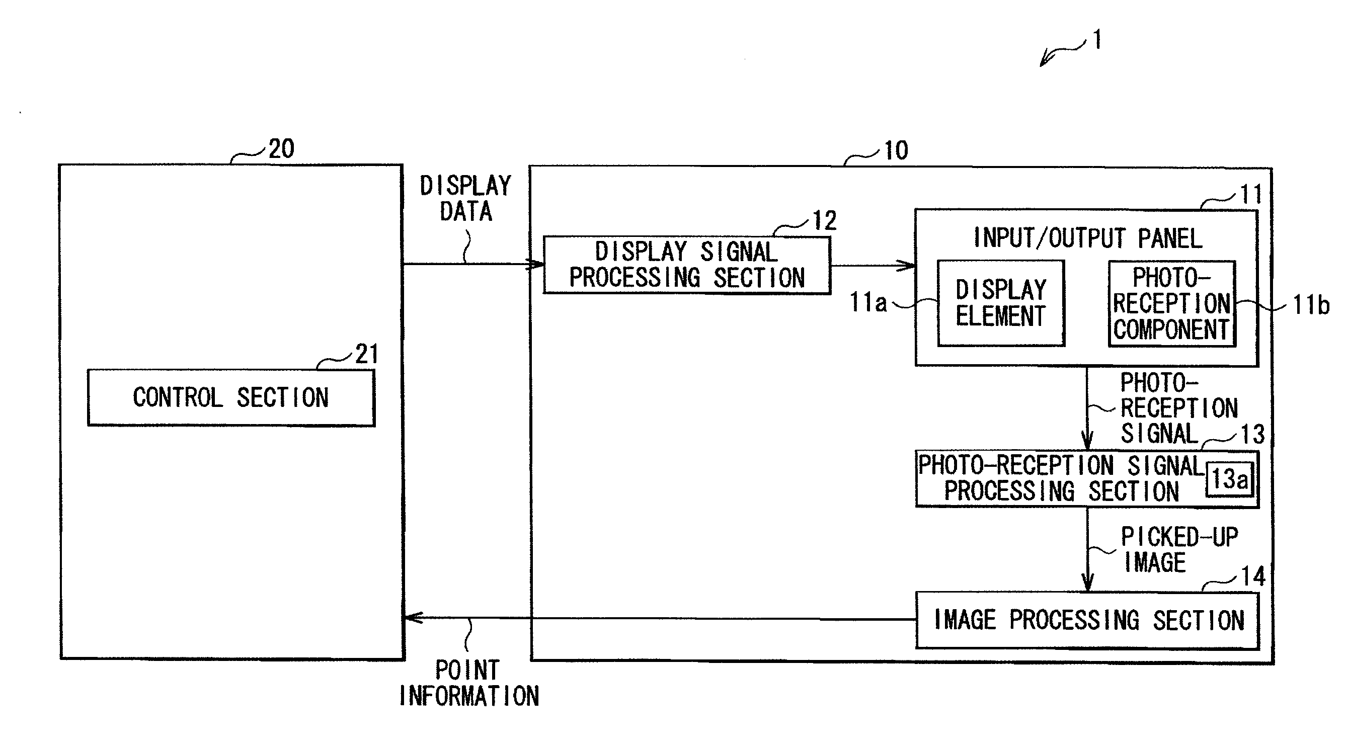
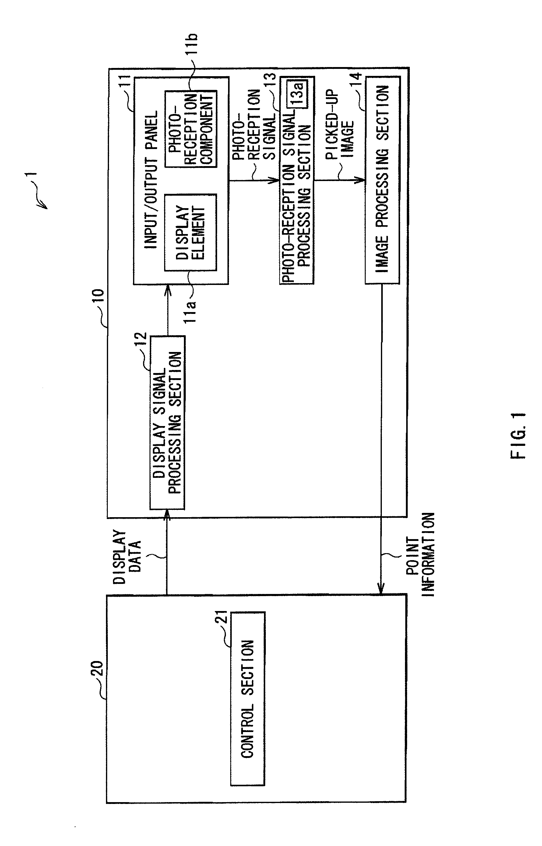
[0064]An image input / output device according to Modification 1 includes a display signal processing section 12, an input / output panel 11, a photo-reception signal processing section 13 and an image processing section 14, which are arranged in a display 10, and a control section 21 arranged in an electric device main body 20 using the display 10.

[0065]In the above-described embodiment, the reference image with a uniform luminance is used when forming the in-plane correction table 13a in the image input / output device according to the embodiment. However, in Modification 1, an arbitrary reference image is displayed on an input / output panel 11, and an in-plane correction table 13a is formed by using the arbitrary reference image. This reference image is arbitrary to have patterns with a plurality of luminance levels in one frame.

[0066]In the configuration of such an image input / output device, the display signal processing section 12 is connected to a previous stage of the input / output p...

modification 2

[0073]FIG. 10 illustrates the configuration of an image input / output device 2 according to Modification 2. The image input / output device 2 differs from the image input / output device 1 according to the embodiment in that an image processing section 14 is arranged in an electric device main body 20. That is, in the image input / output device 2 according to Modification 2, an display signal processing section 12, an input / output panel 11, and a photo-reception signal processing section 13 are arranged in a display 10, and a control section 21 and the image processing section 14 are arranged in the electric device main body 20. Even in such an image input / output device 2, the same effects as in the image input / output device 1 according to the embodiment are obtained.

[0074]In the image input / output devices 1 and 2 described in the embodiment, and Modification 1 and Modification 2, the configuration where a liquid crystal display panel is used as the input / output panel 11 is described. How...


PUM


Abstract

The present invention provides an image input / output device including an input / output panel, a correction section and an image processing section. The input / output panel includes display elements and photo-reception elements to receive lights emitted from the display plane and then reflected from an external adjacent object. The correction section corrects photo-reception signals from the photo-reception elements based on an in-plane correction table where correction coefficients are associated with positions on the display plane, respectively. A value distribution profile in the display plane of the correction coefficients is defined based on both of a light intensity distribution profile of the light emitted from the display plane and a photo-reception sensitivity distribution profile of the photo-reception elements. The image processing section obtains information concerning one or more of position, shape and size of the external adjacent object based on the photo-reception signals corrected by the correction section.

Description

BACKGROUND OF THE INVENTION[0001]1. Field of the Invention[0002]The present invention relates to an image input / output device having an image display function and an image pickup function and a method of inputting images by using the image input / output device, and a method of correcting a photo-reception level in such an image input / output device.[0003]2. Description of the Related Art[0004]In image display devices, there are some display devices including touch panels. In the touch panels, in addition to a resistance type touch panel using a change in electric resistance and a capacitance type touch panel using a change in capacitance, there is an optical type touch panel optically detecting a finger or the like. In the optical type touch panel, for example, light from a backlight is modulated with a liquid crystal element, and an image is displayed on a display plane. Meanwhile, the light emitted from the display plane and reflected by an adjacent object such as a finger is receiv...

Claims


Application Information

Patent Timeline
Patent Type & Authority Applications(United States)
IPC IPC(8): G09G5/00G06F3/041
CPCG06F3/0412G06F3/042G06F3/0418G06F3/04184G06F3/0354G06F3/0421G06F2203/04101
Inventor TSUZAKI, RYOICHIHARADA, TSUTOMUYAMAGUCHI, KAZUNORITATEUCHI, MITSURU
Owner JAPAN DISPLAY WEST
Why Eureka
Try Eureka