Method of controlling touch panel display device and touch panel display device using the same

a touch panel display and touch panel technology, applied in the direction of instruments, computing, electric digital data processing, etc., can solve the problems of exacerbate user operation, inability to accurately control the touch event, and the icon may become too small for a consistent and accurate manipulation by a human finger, so as to facilitate the operation of the zoom function by a user, improve the reliability of registering the touch event, and facilitate the effect of the touch event for a specific icon

Inactive Publication Date: 2010-01-07
LG ELECTRONICS INC
View PDF37 Cites 37 Cited by
  • Summary
  • Abstract
  • Description
  • Claims
  • Application Information

AI Technical Summary

Benefits of technology

[0007]An object of the present invention is to provide a method of controlling a touch panel display device and a touch panel display device using the same, by which a touch event for a specific icon can be facilitated.
[0008]Another object of the present invention is to provide a method of controlling a touch panel display device and a touch panel display device using the same, which improves the reliability of registering a touch event for a specific icon.
[0009]Another object of the present invention is to provide a method of controlling touch panel display device and a touch panel display device using the same, which simplifies t

Problems solved by technology

In many touch panel applications, user operation can be facilitated by displaying a minimum number of icons, which is disadvantageous since fewer icons places undesirable limits on the functionality of a system using a touch panel display device.
To increase the number of simultaneously displayed icons for a given display device, however, icon size should be reduced, which exacerbates user operation and tends to contribute to inputting errors.
In particular, icons may become too small for a consistent and accurate manipulation by a human finger, in which case the system experiences difficulty in rec

Method used


Image

  • Method of controlling touch panel display device and touch panel display device using the same
  • Method of controlling touch panel display device and touch panel display device using the same
  • Method of controlling touch panel display device and touch panel display device using the same

Examples


first embodiment

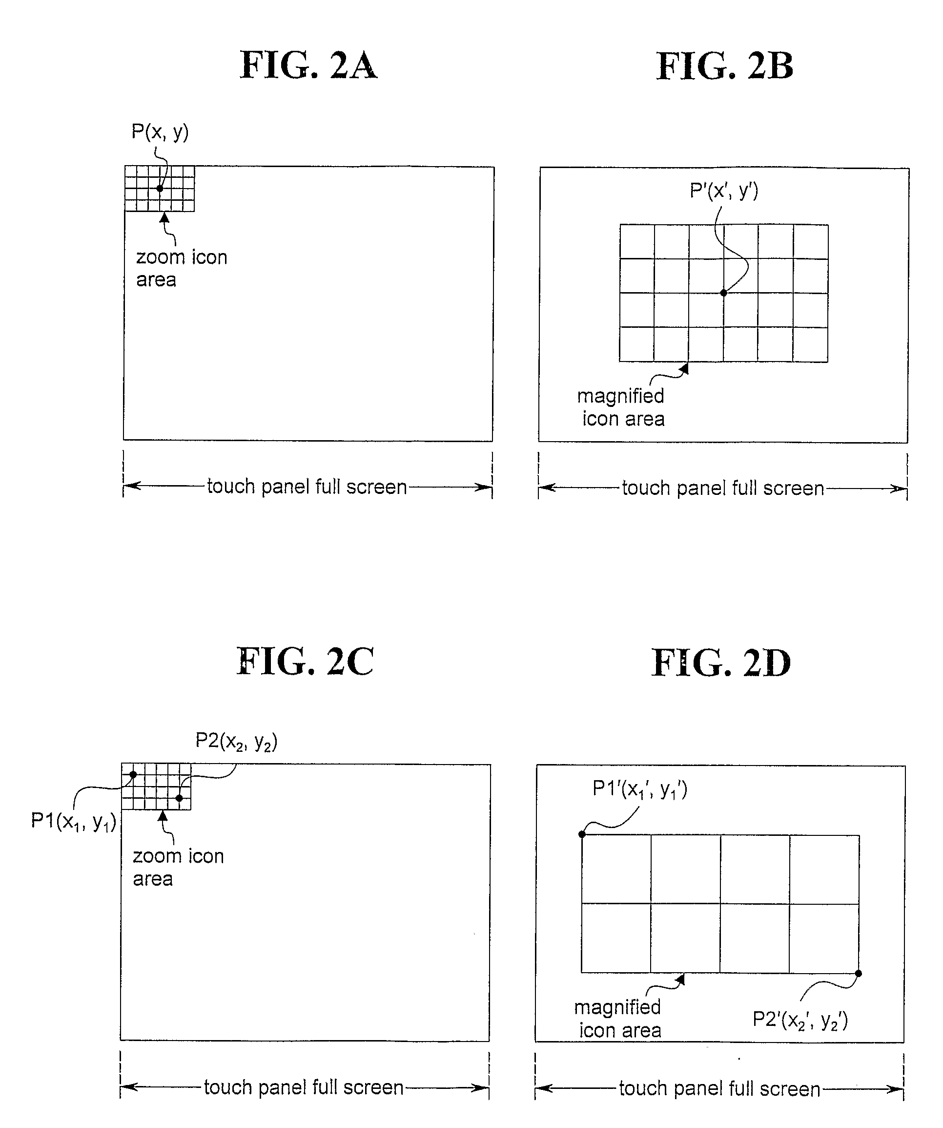
[0030]In FIG. 2A, a zoom icon area is arranged an upper left region of the screen as a block of coordinates corresponding to a set of icons. Upon recognition of a touch event within the zoom icon area, a specific region of the zoom icon area is magnified (scaled) and displayed as in FIG. 2B, to facilitate user recognition of the icons of the zoom icon area and thereby facilitate a quick and accurate selection of a specific icon. Display of the magnified icon area may be achieved by redisplaying the icons of the zoom icon area, centered on coordinates (x, y) of the touched point, and then magnifying the zoom icon area by a prescribed distance, say, ±3 cm, with respect to each coordinate. The PC microprocessor 130a may determine values of new coordinates corresponding to a magnified resolution by multiplying the touched coordinates, i.e., (x, y), by a numerical value to define a magnified icon area based on the new coordinates and generate a scaling control signal for the magnified ic...

second embodiment

[0035]Meanwhile, once a level of magnification has been determined through a zoom function operation achieved by the first or second embodiment, i.e., based on entry of one point or two points, additional zooming (icon area magnification) may be performed according to the process of FIG. 3 (S405, S406). This additional zooming may be necessary in the event of very small icons in very high resolution environments and may be executed using a secondary zoom icon area displayed within the first magnified icon area based on a set of magnified coordinates, and one or more further zooming operations (cycles) may be additionally achieved by executing further iterative processes.

INDUSTRIAL APPLICABILITY

[0036]By adopting the present invention, application of a touch panel display device can be extended by enabling increased reliability of usage by general consumers. In doing so, user errors can be reduced even for small icons in high-resolution (e.g., 1600×1200) environments, thereby facilita...


PUM


Abstract

A method of controlling a touch panel display device, and a touch panel display device using the same, facilitate a user selection (touching) of a specific icon to improve the reliability of registering a touch event for the specific icon, thereby enabling smaller icons to be used with greater accuracy. The touch panel display device includes a touch panel exhibiting a plurality of coordinates corresponding to a screen area of the touch panel display device, the screen area including a zoom icon area; a touch panel controller for recognizing coordinates of a touch event, for storing the recognized coordinates in an internally provided memory, and for outputting a coordinates signal corresponding to the touch event by converting a value generated by the touch event into a corresponding coordinates value; a microprocessor for determining whether the coordinates value output from the touch panel controller corresponds to the zoom icon area of the screen area; a touch driver for outputting a zoom function signal corresponding to the coordinates value output from the touch panel controller; and a display for displaying a magnified icon area corresponding to the zoom icon area, if the microprocessor determines that the coordinates value output from the touch panel controller corresponds to the zoom icon area of the screen area. A method of controlling the above touch panel display device includes steps of displaying a zoom icon area on at least part of a screen made up of a plurality of coordinates; recognizing coordinates of a touch event, to determine whether the touch event corresponds to the displayed zoom icon area; and displaying, if it is determined that the touch event corresponds to the displayed zoom icon area, a magnified icon area corresponding to the zoom icon area.

Description

TECHNICAL FIELD[0001]The present invention relates to touch panel display devices and more particularly to a method of controlling a touch panel display device using a zoom function.BACKGROUND ART[0002]A display device may be provided with a touch panel (also known as a touchscreen or touchscreen panel) as a user interface device enabling such operations as function selection and data input for a variety of apparatuses including personal computers. Such a touch panel display device may be provided in addition to or in lieu of the conventional input devices of a keyboard and mouse. Touch panels are suitable for a variety of applications where the display device itself may be used for system control or data entry, including retail settings such as point-of-sale systems (kiosks) and automated teller machines and in consumer electronics devices such as personal digital assistants and cellular telephones. Touch panels are essentially display overlays enabling the display device to displa...

Claims


Application Information

Patent Timeline
IPC IPC(8): G09G5/00G06F3/041G06F3/048G06F3/0488
CPCG06F3/0416G06F2203/04808G06F2203/04806G06F3/0488G06F3/04817G06F3/0484
Inventor KIM, TAE HOON
Owner LG ELECTRONICS INC
Why Eureka
Try Eureka