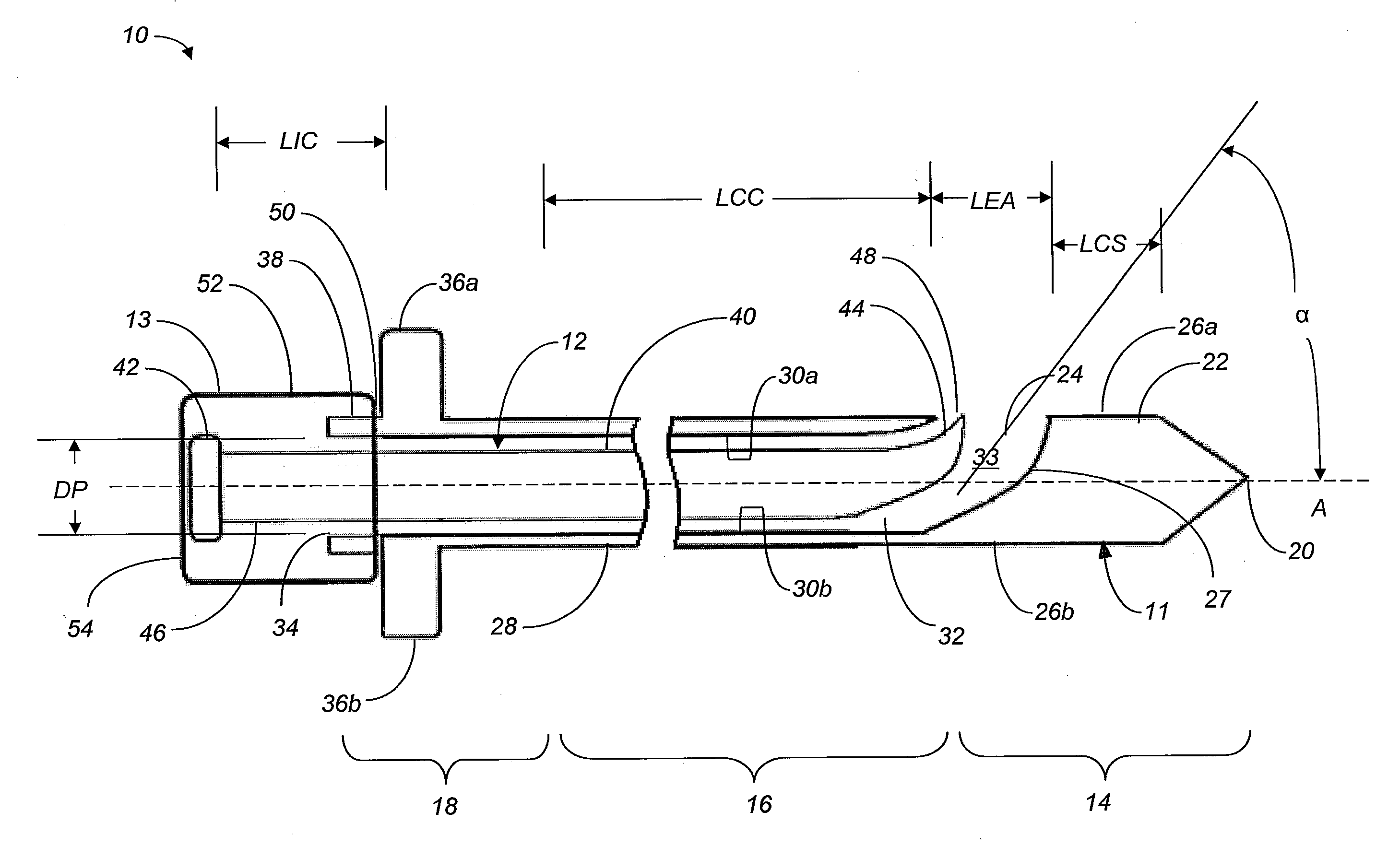
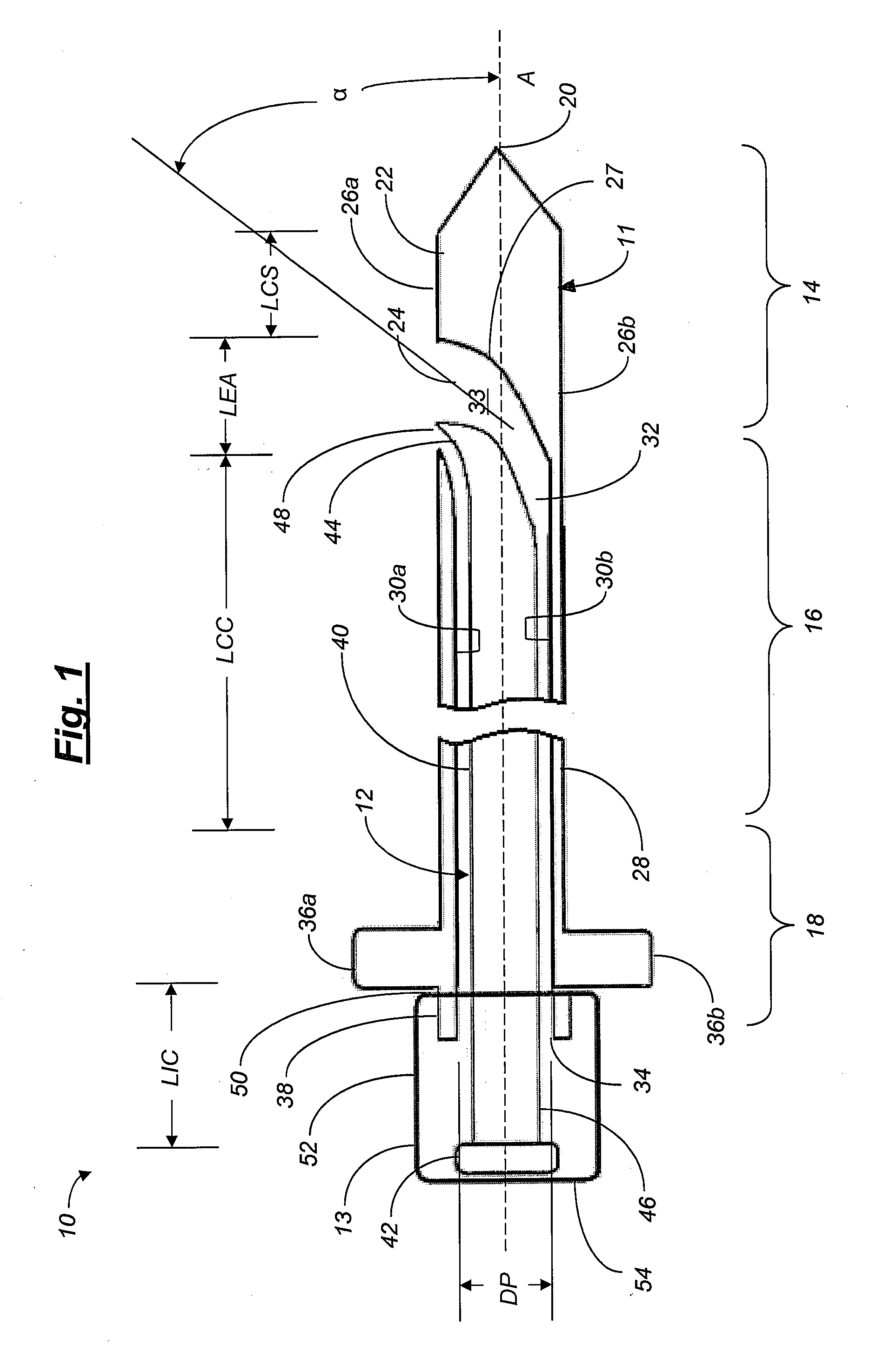
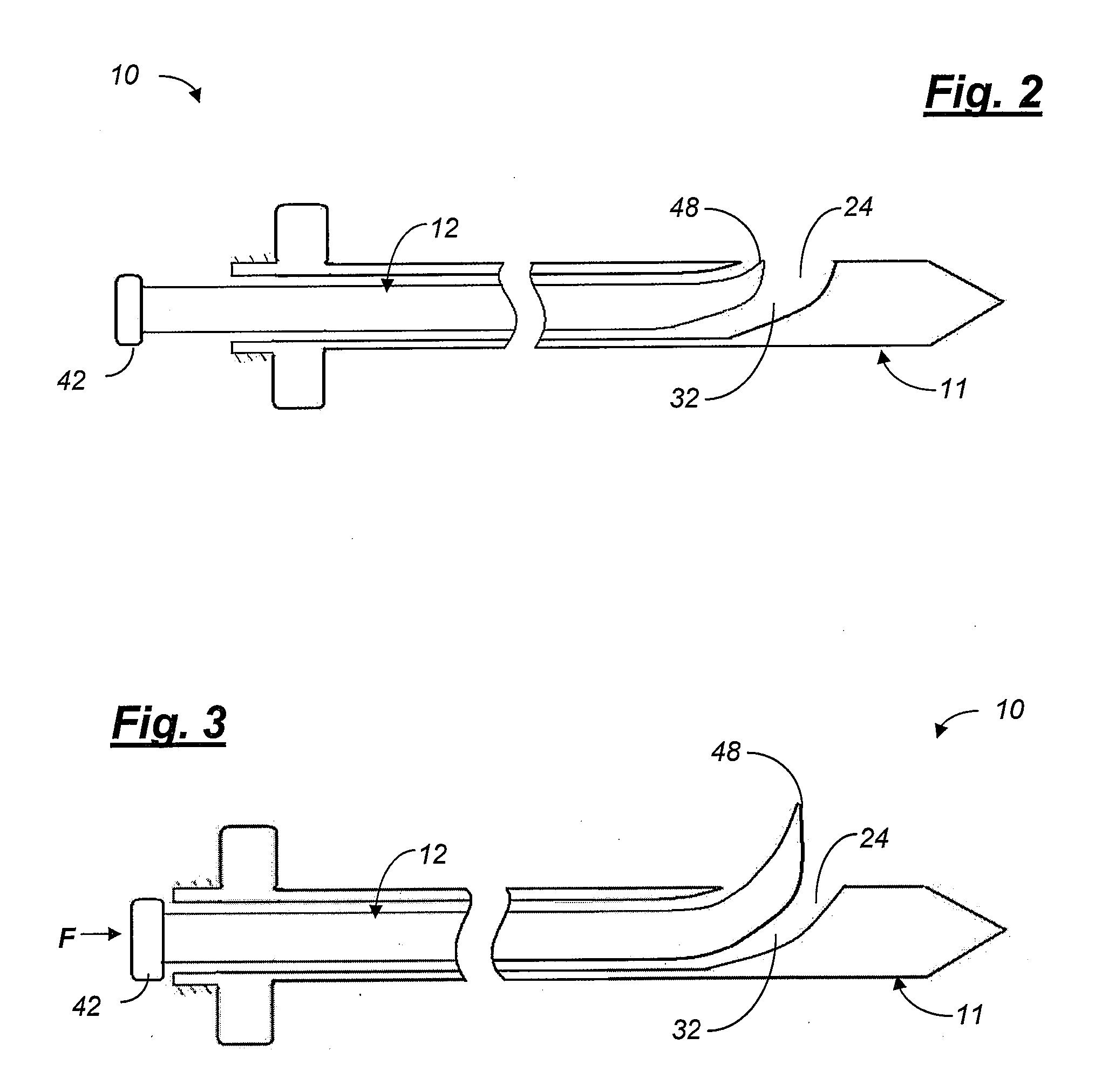
Transpedicular access to the intervertebral disc space for discectomy, end plate preparation, and interbody fusion
a technology of discectomy and transpedicular access, applied in the field of orthopedic surgery, can solve the problems of shortened hospital stay, reduced recovery time, and low incision accuracy, and many minimally invasive fusion techniques have some drawbacks
- Summary
- Abstract
- Description
- Claims
- Application Information
AI Technical Summary
Benefits of technology
Problems solved by technology
Method used
Image
Examples
second embodiment
[0089]As discussed above, the cannula 11 can be formed from a single piece of material or from a plurality of separate components that are joined together. In a second embodiment shown in FIG. 6, a modified insertion device indicated generally at 110 has a cannula 111 that includes a tip 120, a shank portion 122, and an elongated tube 128. In this embodiment, a deflector 127 is provided as a separate component that is attached to the cannula 111 adjacent the cannula shank portion 122. This embodiment advantageously provides for easy replacement of deflectors 127 having different exit angles. Additionally, this embodiment provides for deflectors 127 made of different materials, such as polyetheretherketone (“PEEK”) for example, to be easily installed in the insertion device 110.
third embodiment
[0090]Referring now to FIGS. 7 and 8, an insertion device, indicated generally at 210, is illustrated. The insertion device 210 includes a cannula 211 that includes a proximal end 246 of an obturator 212 that is positioned in a first passage 264 in the cannula 211. The first passage 264 is connected to a second passage 232 in the cannula 211. The first passage 264 defines an angle β with respect to the longitudinal axis A of an elongated tube 228 of the cannula 211. In the illustrated embodiment, the angle β is in a range of from about 15° to about 60°. However, in other embodiments the angle β can be less than about 15° or more than about 60°.
[0091]The cannula 211 includes a cannula head 267. The cannula head 267 is configured to urge the insertion device 210 through the pedicle 60 and through the vertebra 58 while a probe 248 of the obturator 212 is housed substantially within the passages 232 and 264 as described above. The cannula head 267 can have any desired shape sufficient t...
fourth embodiment
[0093]Referring now to FIG. 9, an insertion device, indicated generally at 310, having a cannula 311 is illustrated. In this embodiment, the insertion device 310 is substantially the same as the insertion device 210 illustrated in FIGS. 7 and 8, except that it includes a modified obturator 312 that is itself cannulated, thereby defining a channel 368 within the obturator 312. A guide wire 370 can be positioned within the channel 368. In one embodiment, the guide wire 370 can have a tip 371 having a conical cross-sectional shape forming a sharp point. In other embodiments, the guide wire 370 can have other cross-sectional shapes forming rounded points. In still other embodiments, the guide wire 370 can have a threaded or unthreaded tip 371.
[0094]In one embodiment of a surgical procedure utilizing the insertion device 310, the guide wire 370 is pre-positioned within the channel 368 of the obturator 312 prior to the insertion of the insertion device 310 into the vertebra 58. In other e...
PUM
 Abstract
Description
Claims
Application Information
 - R&D
- Intellectual Property
- Life Sciences
- Materials
- Tech Scout
- Unparalleled Data Quality
- Higher Quality Content
- 60% Fewer Hallucinations
Browse by: Latest US Patents, China's latest patents, Technical Efficacy Thesaurus, Application Domain, Technology Topic, Popular Technical Reports.
© 2025 PatSnap. All rights reserved.Legal|Privacy policy|Modern Slavery Act Transparency Statement|Sitemap|About US| Contact US: help@patsnap.com


