Method and a device for controlling a disc clutch

Active Publication Date: 2010-01-07
VOLVO LASTVAGNAR AB
View PDF27 Cites 3 Cited by
  • Summary
  • Abstract
  • Description
  • Claims
  • Application Information

AI Technical Summary

Benefits of technology

[0004]Automatic Mechanical Transmissions (AMT:s) have become ever more common in heavier vehicles with the increasing development of microprocessor systems, making it possible, with a control computer and a number of control devices, such as servomotors, for example, to precisely regulate the engine speed, engagement and disengagement of an automatic disc clutch between engine and gearbox, and gearbox clutch members in relation to one another, so that smooth gear changes are always achieved at the correct engine speed. The advantage with this type of automatic gearbox compared to a conventional automatic gearbox made up of planetary gear trains and having a hydrodynamic torque converter on the inlet side lies partly in the fact that it is simpler and more robust and can be manufactured at substantially lower cost than the conventional automatic gearbox, especially where used in heavy vehicles, and partly in that it affords greater efficiency, which means scope for reduced fuel consumption.
[0011]There is therefore a need, in a vehicle equipped with an automatic disc clutch, to decrease friction losses and clutch wear.
[0013]The advantage of the method according to the invention is that fuel will be saved and wear of the clutch will be decreased. The same advantages are achieved with an aspect of the invention relating to a device.
[0014]According to an advantageous second embodiment of the method according to the invention said clutch is positioned in said second position when sensing depression of the brake pedal if a brake pedal in the vehicle is depressed before said predetermined time has passed. The advantage of this is that even more fuel can be saved and wear of the clutch can be decreased. The driver indicates that there will not be any vehicle take off when the driver depresses the brake pedal, and thus, the vehicle does not need to be prepared for immediate vehicle take off.

Problems solved by technology

This means that fuel is consumed for purely warming up and wearing down the clutch.

Method used


Image

  • Method and a device for controlling a disc clutch
  • Method and a device for controlling a disc clutch
  • Method and a device for controlling a disc clutch

Examples


Embodiment Construction

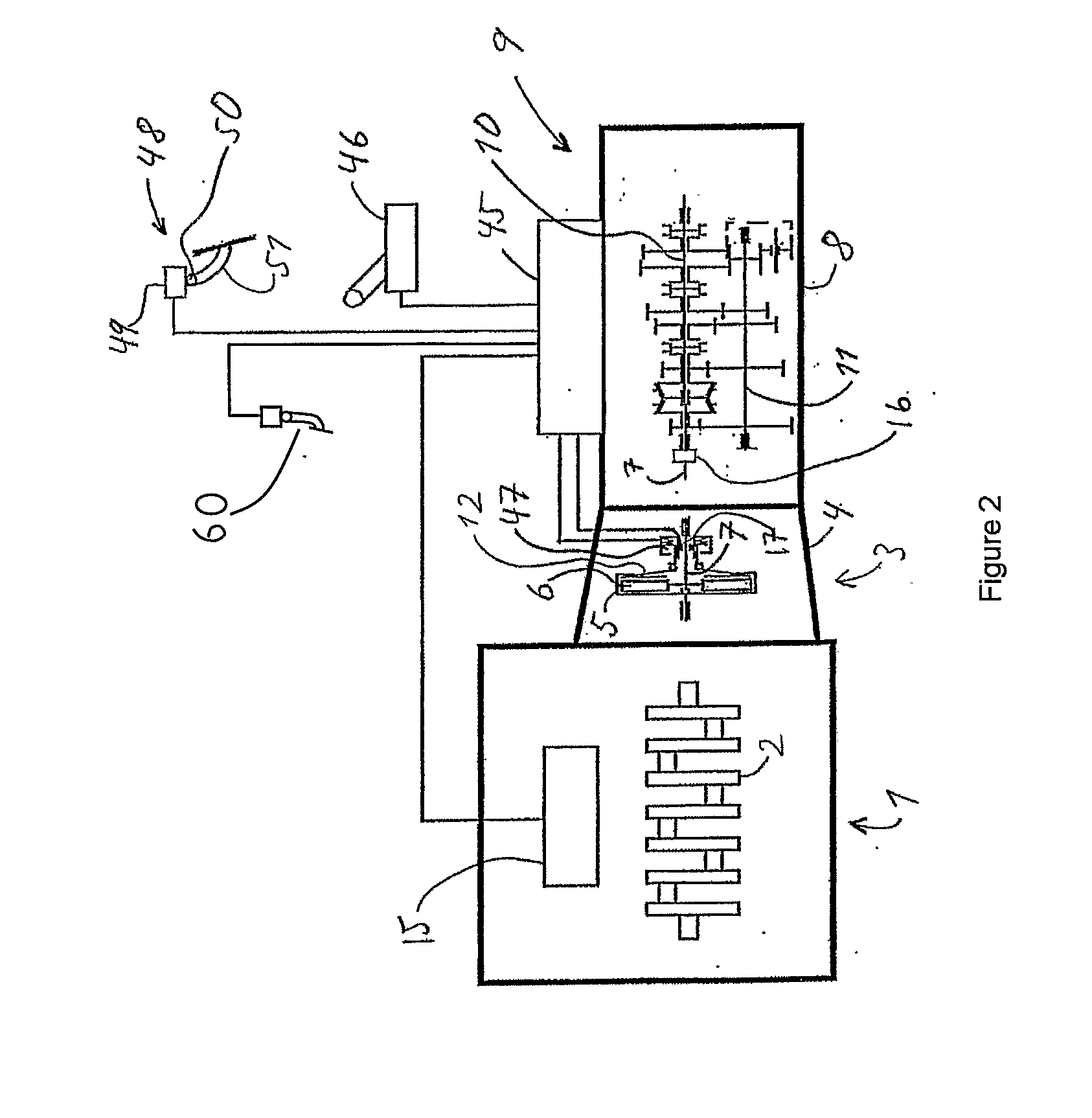
[0020]In FIG. 2, 1 denotes a six-cylinder internal combustion engine, for example a Diesel engine, the crankshaft 2 of which is coupled to a single-disc dry clutch generally denoted by 3, which is enclosed in a clutch cover 4. Depending on the magnitude of the maximum torque to be transmitted by the clutch, the clutch may have more than one disc and pressure plate 12. The crankshaft 2 is rotationally fixed to the clutch housing 5 of the clutch 3, while the disc 6 thereof is rotationally fixed to an input shaft 7, which is rotatably supported in a gearbox housing 8 of a gearbox generally denoted by 9. A main shaft 10 and an intermediate shaft 11 are also rotatably supported in the housing 8.

[0021]Servo devices (not shown) in the gearbox, which engage and disengage the different gears in the gearbox 9, are controlled by an electronic control unit 45 as a function of control unit input signals representing various engine and vehicle data. Among other things, the control unit 45 compris...


PUM


Abstract

In a method and a control unit for controlling the position of an automatic disc clutch in a vehicle, which disc clutch is arranged to transmit motive force from an internal combustion engine to an input shaft of a stagegeared gearbox in the vehicle, the control unit is arranged to position the clutch in a first position, preparing the vehicle for take off, with the gearbox having a starting gear engaged, and where the clutch in the first position transmits a smaller torque, characterized in that the control unit being further arranged to position the clutch in a second more disengaged position compared to the first position, if a driver of the vehicle does not demand vehicle take off torque by activating a throttle control within a predetermined time.

Description

BACKGROUND AND SUMMARY[0001]The present invention relates to a method of controlling an automatic disc clutch, the disc clutch being arranged in a motor vehicle in order to transmit motive force from an internal combustion engine to a gearbox.[0002]The invention also relates to a control unit for controlling an automatic disc clutch.[0003]The invention also relates to a computer program for carrying out said method.[0004]Automatic Mechanical Transmissions (AMT:s) have become ever more common in heavier vehicles with the increasing development of microprocessor systems, making it possible, with a control computer and a number of control devices, such as servomotors, for example, to precisely regulate the engine speed, engagement and disengagement of an automatic disc clutch between engine and gearbox, and gearbox clutch members in relation to one another, so that smooth gear changes are always achieved at the correct engine speed. The advantage with this type of automatic gearbox com...

Claims


Application Information

Patent Timeline
IPC IPC(8): G06F17/00F16D48/06
CPCF16D48/08F16D2500/3026F16D2500/31426F16D2500/3144F16D2500/50224Y10T477/641F16D2500/7041F16D2500/70414Y10T477/745Y10T477/78Y10T477/79F16D2500/5126
Inventor KARLSSON, SVANTELAURI, ERIK
Owner VOLVO LASTVAGNAR AB
Why Eureka
Try Eureka