A method for braking a vehicle

Active Publication Date: 2015-07-09
SCANIA CV AB
View PDF2 Cites 0 Cited by
  • Summary
  • Abstract
  • Description
  • Claims
  • Application Information

AI Technical Summary

Benefits of technology

[0008]This braking is used when driving with a so-called free planetary gear (the locking means in the releasing position) at a little higher speeds. The most usual reason to drive the vehicle with free planetary gear at higher speeds is to save fuel at low propulsion system torques by letting the combustion engine run with low rotational speeds. When applying a brake torque through the electric machine exceeding said product, the rotational speed of the combustion engine will increase, which according to the invention is utilized for obtaining a smooth braking due to increasing the rotational speed of the combustion engine so that the first component gets a rotational speed synchronous with respect to the third component and the input shaft of the gearbox without any need to use fuel. When the planetary gear is then locked (its locking means is in the locking position) the electric machine may brake by an optional torque, which may then be chosen to be high, if desired. Braking while regenerating braking energy may be carried out very energy efficiently. It is pointed out that braking the vehicle is made with the torque that is requested and that is possible to apply and is not targeted by a torque exceeding said product. It is a problem when braking with so-called free planet that only a restricted brake torque may be applied, since when this exceeds said product and the rotational speed of the

Problems solved by technology

It is a problem when braking with so-called free planet that only a restricted brake torque may be a

Method used


Image

  • A method for braking a vehicle
  • A method for braking a vehicle
  • A method for braking a vehicle

Examples


Example

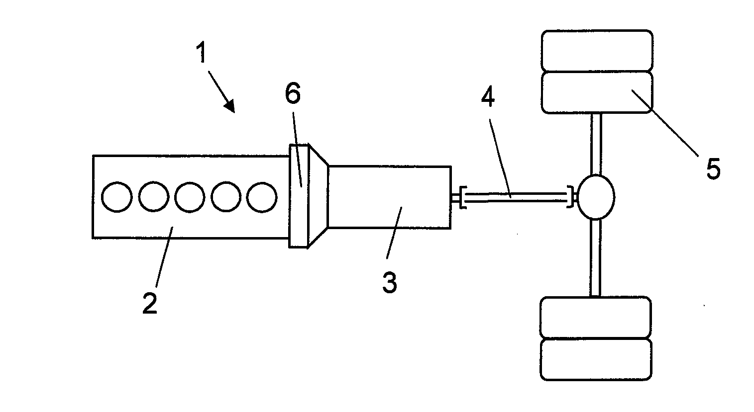
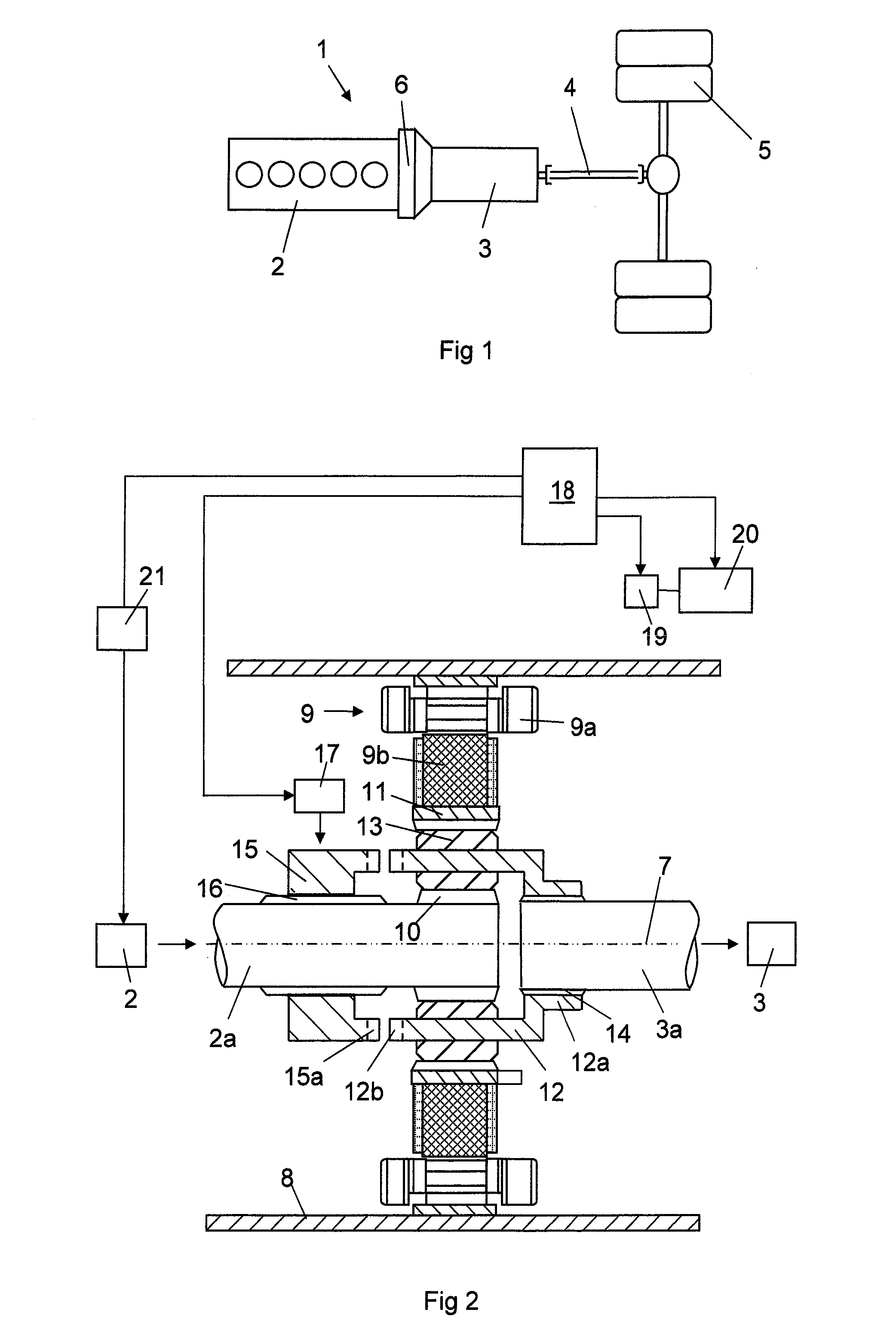
[0022]FIG. 1 shows a drivetrain for a heavy vehicle 1. The drivetrain comprises a combustion engine 2, a gearbox 3, a number of drive shafts 4 and drive wheels 5. The drivetrain has between the combustion engine 2 and the gearbox 3 an intermediate portion 6. FIG. 2 shows more in detail the components in the intermediate portion 6. The combustion engine 2 is provided with an output shaft 2a and the gearbox 3 with an input shaft 3a in the intermediate portion 6. The output shaft 2a of the combustion engine is arranged coaxially with respect to the input shaft 3a of the gearbox. The output shaft 2a of the combustion engine and the input shaft 3a of the gearbox are arranged to rotate around a rotation axis 7 in common. The intermediate portion 6 comprises a housing 8 enclosing an electric machine 9 and a planetary gear. The electric machine 9 comprises as usual a stator 9a and a rotor 9b. The stator 9a comprises a stator core secured in a suitable way on the inner side of the housing 8....


PUM


Abstract

A method for braking a vehicle driving forward, in which the vehicle has a propulsion system including a combustion engine with an output shaft (2a), a gearbox (3) with an input shaft (3a), an electric machine (9) comprising a stator and a rotor, and a planetary gear comprising three components in the form of a sun gear (10), a ring gear (11) and a planet wheel carrier (12). The vehicle is driven with one of the components connected to an output shaft of the combustion engine rotating with a lower rotational speed than one of the components connected to the electric machine. When the vehicle is braked, the electric machine is controlled to apply a brake torque to the input shaft of the gearbox, making the rotational speed of the combustion engine increase.

Description

CROSS-REFERENCE TO RELATED APPLICATIONS[0001]The present application is a 35 U.S.C. §§371 National Phase conversion of PCT / SE2013 / 050774, filed Jun. 26, 2013, which claims priority of Swedish Patent Application No. 1250706-7, filed Jun. 27, 2012, the contents of which are incorporated by reference herein. The PCT International Application was published in the English language.FIELD OF THE INVENTION AND PRIOR ART[0002]The present invention relates to a method for braking a vehicle driving forward.[0003]The invention is especially but not exclusively directed to carrying out such a method for motor vehicles in the form of wheeled utility vehicles, especially heavy vehicles, such as trucks and buses.[0004]Accordingly, the invention relates to a method for braking a hybrid vehicle driving forward, in which such a vehicle is generally a vehicle which may be driven by a primary engine, here a combustion engine, and a secondary engine, here an electric machine. The electric machine is suit...

Claims


Application Information

Patent Timeline
IPC IPC(8): B60W20/00B60W10/08B60W10/115B60W30/18
CPCB60W20/108B60W30/18127Y10S903/93B60W10/115B60W10/08B60K6/365B60L7/20B60L15/2009B60L15/2054B60L2240/12B60L2240/421B60L2240/423B60L2240/441B60K6/48B60W30/18136B60W20/15Y02T10/72B60W20/00Y02T10/62Y02T10/64B60W10/11B60W10/18B60L7/10B60W20/30
Inventor PETTERSSON, NIKLASBERGQUIST, MIKAELLINDSTROM, JOHANKJELL, ANDERSBJORKMAN, MATHIAS
Owner SCANIA CV AB
Why Eureka
Try Eureka