Gas distribution plate and substrate treating apparatus including the same

a technology of gas distribution plate and substrate, which is applied in the direction of chemical vapor deposition coating, metal material coating process, coating, etc., can solve the problems of reduced production efficiency, difficult to obtain etching uniformity, and degraded thin film uniformity, so as to improve the uniformity of thin film and production efficiency

Active Publication Date: 2010-01-14
JUSUNG ENG
View PDF2 Cites 411 Cited by
  • Summary
  • Abstract
  • Description
  • Claims
  • Application Information

AI Technical Summary

Benefits of technology

[0016]An advantage of the present invention is to provide a gas distribution plate and a substrate treating apparatus including the same which can improve uniformity of a thin film and production efficiency.

Problems solved by technology

Further, when the thin film on the substrate 2 is etched, etching uniformity is difficult to obtain.
Therefore, uniformity of the thin film is degraded and production efficiency is reduced.

Method used


Image

  • Gas distribution plate and substrate treating apparatus including the same
  • Gas distribution plate and substrate treating apparatus including the same
  • Gas distribution plate and substrate treating apparatus including the same

Examples


first embodiment

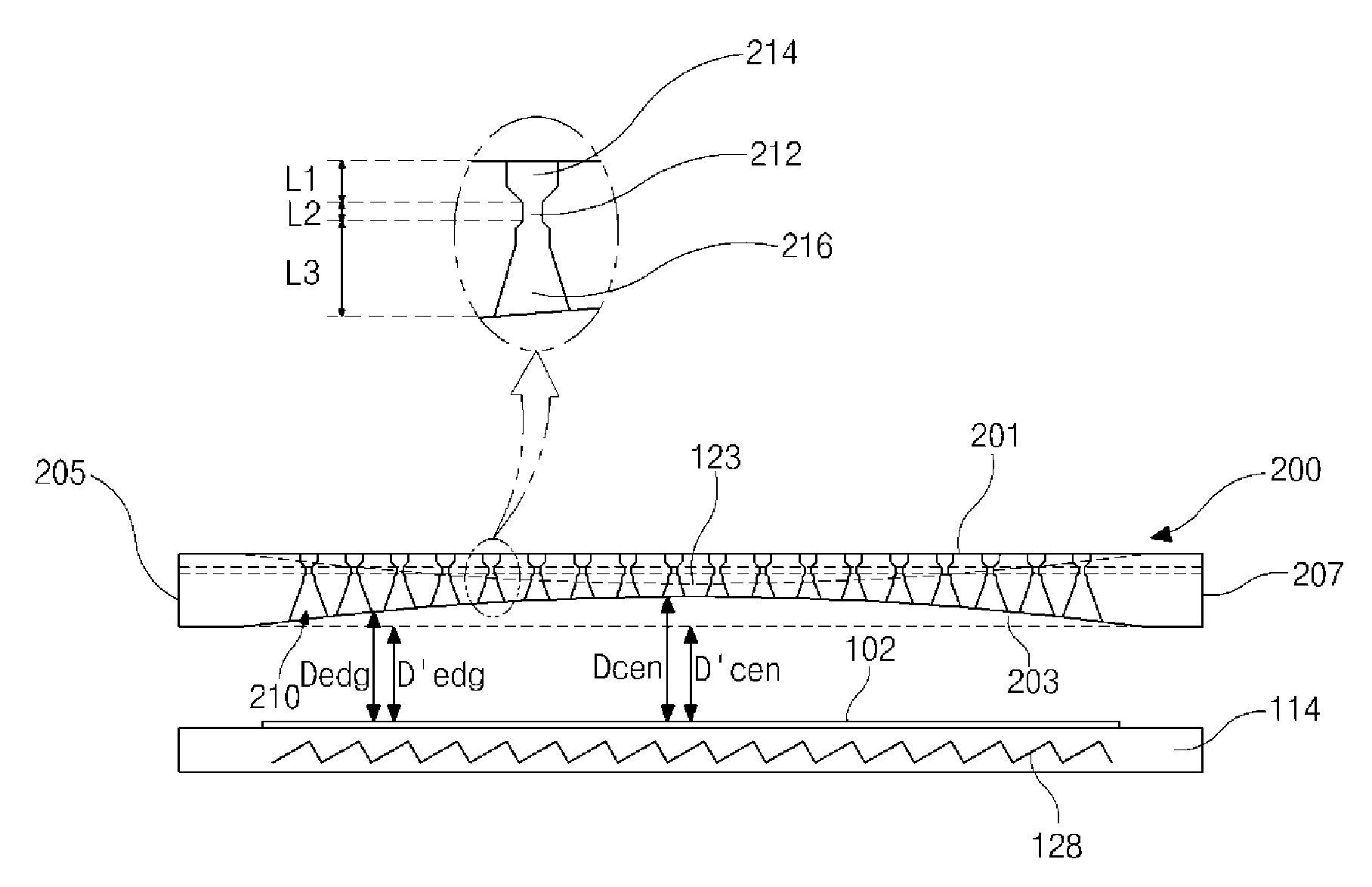
[0034]Referring to FIGS. 3 to 5, the gas distribution plate 200 of the substrate treating apparatus includes a first surface 201 referred to as a top surface, a second surface 203 referred to as a bottom surface, and first and second side surfaces 205 and 207. The first surface 201 may be parallel with the substrate placing plate 114. The second surface 203 faces the substrate placing plate 114 and has a recess shape, for example, a concave recess shape. The gas distribution plate 200 have a plurality of injection holes 210 to inject a reaction gas toward a substrate 102 placed on the substrate placing plate 114. The gas distribution plate 200 and the substrate placing plate 114 are located in a chamber (not shown) providing a reaction space (not shown). The gas distribution plate 200 and the substrate placing plate 114 may have substantially the same shape in plane, for example, a circular or rectangular shape.

[0035]Each injection hole 210 may include an inflow portion 214, an ori...

second embodiment

[0046]To solve this problem, a second embodiment is provided as follows.

[0047]FIG. 6 is a cross-sectional view illustrating a substrate treating apparatus according to the second embodiment of the present invention, FIG. 7 is a cross-sectional view illustrating a gas distribution plate and a substrate placing plate according to the second embodiment of the present invention, FIG. 8 is a cross-sectional view enlarging a portion of the gas distribution plate according to the second embodiment of the present invention, FIGS. 9 and 10 are cross-sectional views illustrating top and bottom surfaces, respectively, of the gas distribution plate according to the second embodiment of the present invention. Explanations of parts similar to parts of the first embodiment may be omitted.

[0048]Referring to FIGS. 6 to 10, the substrate treating apparatus 110 according to the second embodiment includes a chamber 111 including a chamber lid 112 and providing a reaction space E therein. The substrate ...

third embodiment

[0066]Referring to FIGS. 10 and 11, the gas distribution plate 200 of the substrate treating apparatus includes a first surface 201 referred to as a top surface, a second surface 203 referred to as a bottom surface, and first and second side surfaces 205 and 207. The first surface 201 may be parallel with a substrate placing plate 114. The second surface 203 faces the substrate placing plate 114 and has a recess shape, for example, a stepped recess shape. The gas distribution plate 200 have a plurality of injection holes 410 to inject a reaction gas toward a substrate 102 placed on the substrate placing plate 114. The gas distribution plate 200 and the substrate placing plate 114 are located in a chamber providing a reaction space. The gas distribution plate 200 and the substrate placing plate 114 may have substantially the same shape in plane, for example, a circular or rectangular shape.

[0067]The second surface 203 may include a plurality of steps, and a number of the steps is no...


PUM

PropertyMeasurementUnit
distanceaaaaaaaaaa
diameteraaaaaaaaaa
volumeaaaaaaaaaa

Abstract

A gas distribution plate that is installed in a chamber providing a reaction space and supplies a reaction gas onto a substrate placed on a substrate placing plate, wherein the gas distribution plate includes: first and second surfaces opposing to each other, wherein the second surface faces the substrate placing plate and has a recess shape; and a plurality of injection holes each including: an inflow portion that extends from the first surface toward the second surface; a diffusing portion that extends from the second surface toward the first surface; and an orifice portion between the inflow portion and the diffusing portion, wherein the plurality of inflow portions of the plurality of injection holes decrease in gas path from edge to middle of the gas distribution plate, and wherein the plurality of diffusing portions of the plurality of injection holes have substantially the same gas path.

Description

[0001]The present invention claims benefit of Korean Patent Application Nos. 10-2008-0065816, and 10-2009-0053463 filed in Korea on Jul. 8, 2008, and Jun. 16, 2009, respectively, which are hereby incorporated by reference.BACKGROUND OF THE INVENTION[0002]1. Field of the Invention[0003]The present invention relates to a gas distribution plate and a substrate treating apparatus including the same.[0004]2. Background of the Related Art[0005]In general, semiconductor devices, display devices, solar cells, and the like are manufactured through various processes for substrates. For example, a thin film deposition process and a photolithography process and an etching process are performed several times to form circuit patterns on the substrate, and additional processes such as a cleaning process, an attaching process, a cutting process and the like are performed. Among these processes, the deposition process and the etching process are performed in a chamber type substrate treating apparat...

Claims


Application Information

Patent Timeline
Patent Type & Authority Applications(United States)
IPC IPC(8): C23C16/54
CPCC23C16/45565
Inventor CHOI, JAE-WOOKPARK, CHAN-HO
Owner JUSUNG ENG
Why Eureka
Try Eureka