Water scavenging system

a water scavenging and water tank technology, applied in machine/engine, separation process, filtration separation, etc., can solve the problems of icing in the tank, water only being fully removed,

Inactive Publication Date: 2010-01-14
AIRBUS OPERATIONS LTD
View PDF5 Cites 9 Cited by
  • Summary
  • Abstract
  • Description
  • Claims
  • Application Information

AI Technical Summary

Benefits of technology

[0006]The water scavenging system may be powered electrically, but more preferably is powered by the hydr

Problems solved by technology

A problem with the arrangement of U.S. Pat. No. 4,809,934 is that the water will only be fully removed when the fuel tan

Method used


Image

  • Water scavenging system
  • Water scavenging system
  • Water scavenging system

Examples


Embodiment Construction

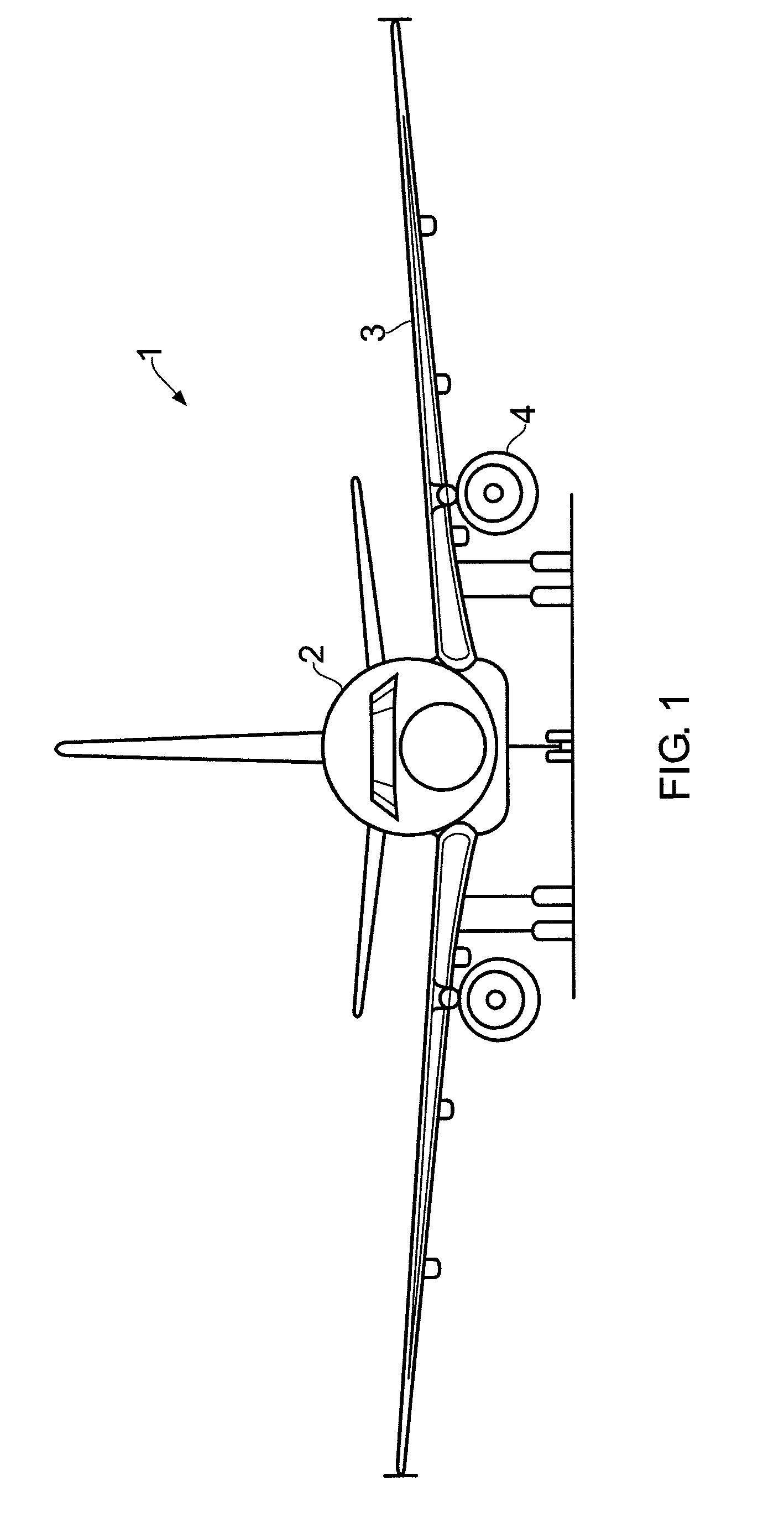
[0017]Referring to FIG. 1, an aircraft 1 comprises a fuselage 2 carrying a pair of wings, the left wing being labelled 3. Each wing carries an engine, the left hand engine being labelled 4 in FIG. 1. The engine includes a high pressure fuel pump (not shown) which requires a minimum inlet pressure, typically of the order of 5-10 psig.

[0018]Fuel for each engine is stored in a centre tank and one or more wing tanks. In the example given below, only a single wing tank is described, but in practice there are additional wing tanks.

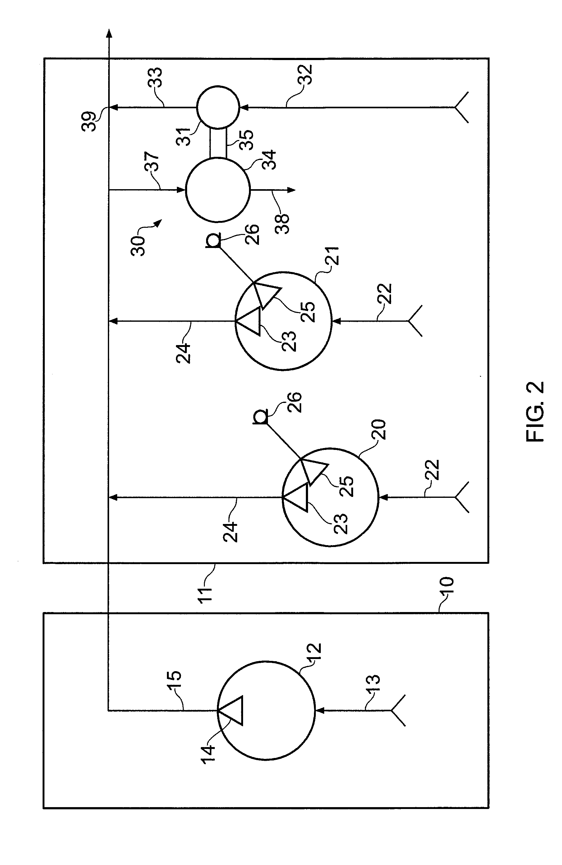
[0019]FIG. 2 is a schematic diagram showing the centre tank 10 and a wing tank 11 for the left hand wing 3.

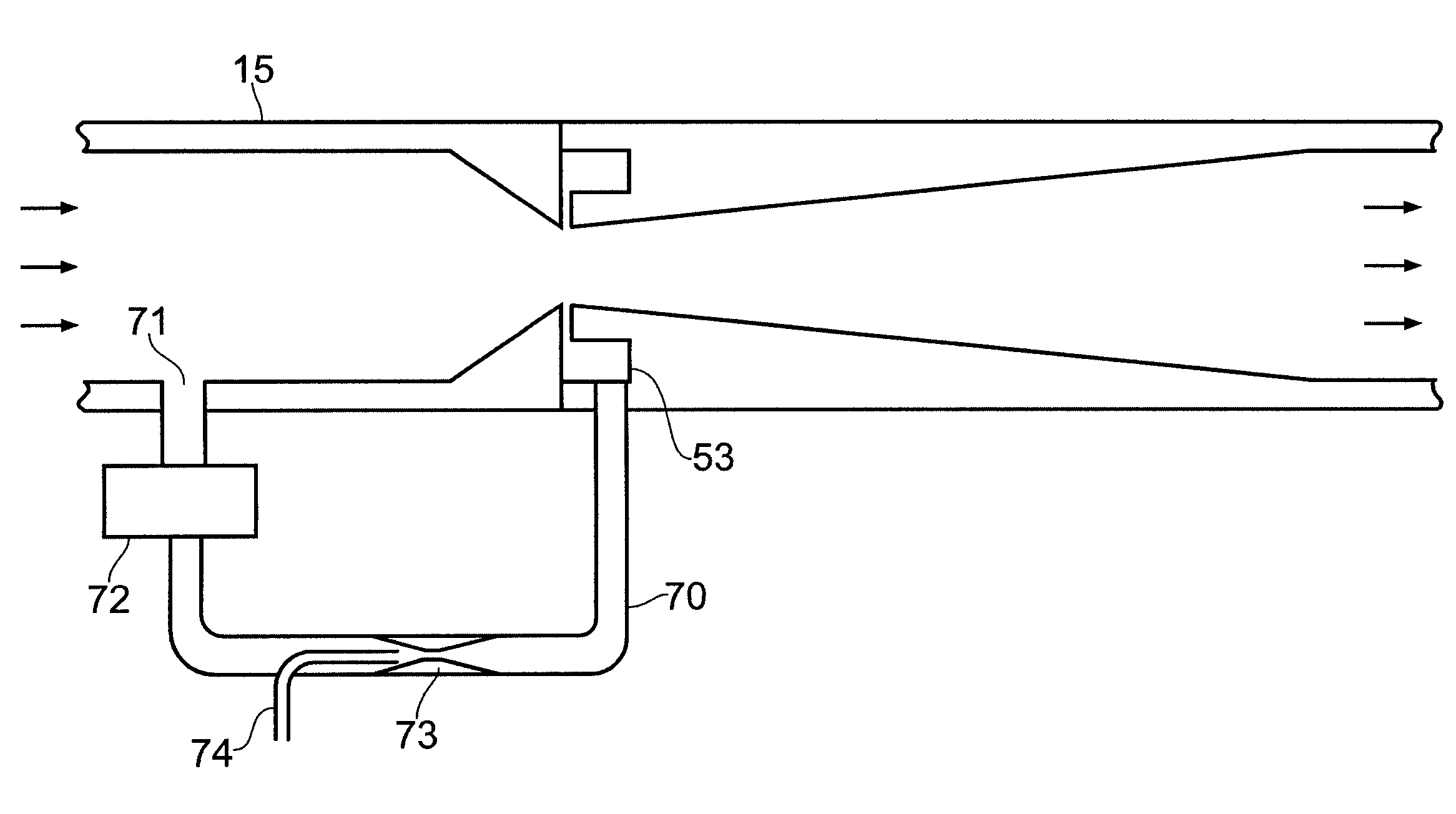
[0020]The centre tank 10 has a fuel pump 12 having an inlet 13 for collecting fuel from the tank 10, and an outlet 14 that incorporates a non return valve to prevent flow back into the pump, coupled in series to a fuel line 15 which leads to the engine 4.

[0021]The wing tank 11 comprises a pair of fuel pumps 20, 21 which are identical in construction (and ar...


PUM

PropertyMeasurementUnit
Poweraaaaaaaaaa
Circumferenceaaaaaaaaaa

Abstract

A fuel system comprising: a fuel line coupled to an engine; a fuel pump having an inlet coupled to a fuel tank and an outlet coupled to the fuel line; and a water scavenging system having an inlet for collecting water and an outlet coupled to the fuel line in parallel with the pump. The water scavenging system is powered by the hydraulic action of fuel in the fuel line using for example a venturi arrangement or a motor/pump combination.

Description

FIELD OF THE INVENTION[0001]The present invention relates to a method and apparatus for removing water from a fuel tank.BACKGROUND OF THE INVENTION[0002]U.S. Pat. No. 4,809,934 describes a system for on-board disposal of water in aircraft fuel tanks. Water is drawn into a jet pump and dispersed into a fuel tank for consumption by the aircraft engines. A problem with the arrangement of U.S. Pat. No. 4,809,934 is that the water will only be fully removed when the fuel tank is empty. Also, the water dispersed in the fuel tank may create “snow” or cause icing in the tank at lower temperatures.SUMMARY OF THE INVENTION[0003]A first aspect of the invention provides a fuel system comprising: a fuel line; a fuel pump having an inlet coupled to a fuel tank and an outlet coupled to the fuel line; and a water scavenging system having an inlet for collecting water from the fuel tank and an outlet coupled to the fuel line in parallel with the pump.[0004]A second aspect of the invention provides a...

Claims


Application Information

Patent Timeline
IPC IPC(8): F02M25/00F02B47/02E03B11/16
CPCB64D37/34Y10T137/85978
Inventor MINTY, ANDREWMILES, BARRY
Owner AIRBUS OPERATIONS LTD
Why Eureka
Try Eureka