Vibration damping system

a vibration damping and damping technology, applied in the direction of shock absorbers, machine supports, transportation and packaging, etc., can solve the problems of inability to deform, increase the isostatic stress in the inside, and fracture the soft member, so as to achieve the effect of preventing damages

Inactive Publication Date: 2010-01-14
BRIDGESTONE CORP
View PDF7 Cites 16 Cited by
  • Summary
  • Abstract
  • Description
  • Claims
  • Application Information

AI Technical Summary

Benefits of technology

[0026]It is preferred that the opening cross-sectional area of the injection gate is proportionally variable in accordance with the change in thickness of the soft members. In this instance, it is possible to more positively achieve the above-mentioned functional effects of the invention.
[0027]As explained above, the present invention provides a vibration damping system and a method for producing such a structure, wherein occurrence of damages can be effectively prevented even when vibration with a large amplitude in the shearing direction is input and a prying deformation is caused. This is the most significant effect of the present invention.

Problems solved by technology

In the case of a vibration damping system including a hybrid laminated body wherein a plurality of hard plates having a rigidity, and a plurality of soft members having a viscoelasticity are alternately laminated with each other; although the structure exhibits a high durability against compression, there may be caused a fracture of the soft members when a tensile load is applied.
This is because the soft members when applied with a tensile load do not exhibit a change in volume due to its incompressibility, with the result that the isostatic stress increases in the inside which cannot be deformed.

Method used


Image

  • Vibration damping system
  • Vibration damping system
  • Vibration damping system

Examples


first embodiment

Vibration Damping System

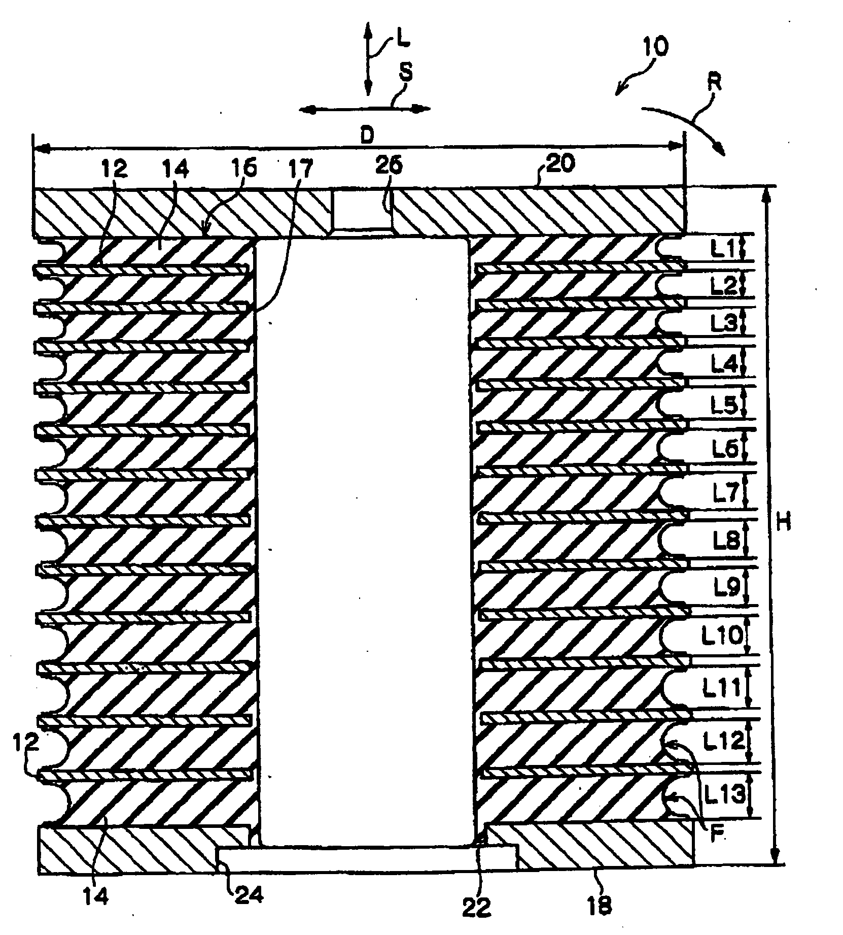
[0050]There is shown in FIG. 1 a first embodiment of the vibration damping system 10 according to the present invention. The vibration damping system 10 includes a laminated rubber member 16 in the form of a hybrid laminated body wherein a plurality of hard plates 12, which can be regarded essentially as a rigid body, and a plurality of rubber plates 14 as soft members (e.g., 13 layers as in the illustrated embodiment) are alternately laminated with each other.

[0051]The laminated rubber body 16 is in the form of a thick-walled cylinder having in its center region a columnar cavity 17 that extends through the laminated rubber body 16 in the laminating direction. That is to say, the hard plates 12 and the rubber plates 14 are each formed into an annular shape and adhered to each other by vulcanization so as to be integrated as the laminated rubber body 16.

[0052]The hard plates 12 forming part of the laminated rubber body 16 may be comprised of a suitable metal ...

second embodiment

Vibration Damping System

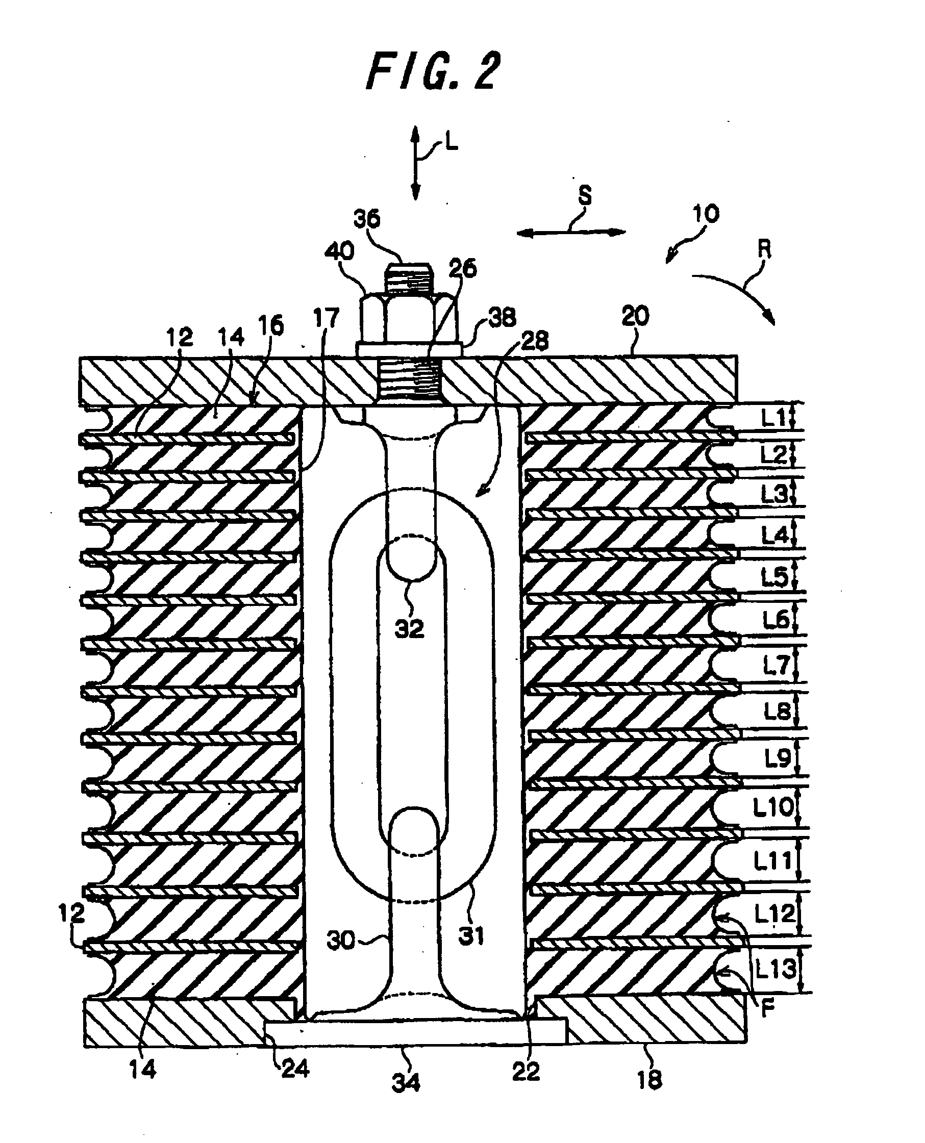
[0067]A second embodiment of the vibration damping system according to the present invention will be described below with reference to FIGS. 2 and 3. Those elements already described with reference to the first embodiment are denoted by the same reference numerals to eliminate an overlapping description. The vibration damping system according to the second embodiment has a structure in which, as shown in FIGS. 2 and 3, a displacement restriction member in the form of a metal link chain 28 is arranged in the cavity 17 of the laminated rubber body 16, as opposed to the first embodiment in which the cavity 17 in the laminated rubber body 16 is left vacant.

[0068]The link chain 28 is arranged so that its longitudinal axis coincides with the laminating direction of the laminated rubber body 16, and has sufficiently high rigidity and strength to a tensile load in the laminating direction, as compared to the laminated rubber body 16. The link chain comprises a plural...


PUM

PropertyMeasurementUnit
diameteraaaaaaaaaa
total heightaaaaaaaaaa
heightaaaaaaaaaa

Abstract

A vibration damping system (10) includes a laminated body (16) formed by alternately laminating rigid hard plates (12) and viscoelastic soft plates (14). At both ends in the laminating direction, the laminated body (16) is connected to a vibration generation section and a vibration receiving section, respectively. The soft plate (14) arranged in a region subjected to a higher isostatic stress is made thicker than the soft plates (14) arranged in other regions. Even when the vibration damping system (10) is applied with vibration having a large amplitude and prying deformation is thereby caused, the soft members (14) are prevented from isostatic fracture to provide a significantly improved durability of the vibration damping system (10).

Description

TECHNICAL FIELD[0001]The present invention relates to a vibration damping system comprising a laminated body including a plurality of hard plates having a rigidity, and a plurality of soft members having a viscoelasticity, wherein the hard plates and the soft members are alternately laminated with each other.BACKGROUND ART[0002]Conventionally, in order to damp and absorb vibrations transmitted from a vibration generating section, such as a linkage for supporting a load-carrying platform or the like, to a vibration receiving section, such as an axle or the like, there is an instance in which a vibration damping system is arranged between the vibration generating section and the vibration receiving section, wherein the vibration damping system is comprised of a laminated body including a plurality of hard plates having a rigidity, and a plurality of soft members having a viscoelasticity, with the hard plates and the soft members being alternately laminated with each other. When a vibr...

Claims


Application Information

Patent Timeline
Patent Type & Authority Applications(United States)
IPC IPC(8): F16M7/00B29C45/14B29C45/26
CPCF16F2230/007F16F1/406
Inventor KAWADA, MASAYOSHI
Owner BRIDGESTONE CORP
Why Eureka
Try Eureka