Angle detecting apparatus and angle detecting method

Inactive Publication Date: 2010-01-14
TDK CORPARATION
View PDF2 Cites 29 Cited by
  • Summary
  • Abstract
  • Description
  • Claims
  • Application Information

AI Technical Summary

Benefits of technology

[0019]The present invention can provide an angle detecting apparatus and an angle detecting

Problems solved by technology

However, the above-described angle of rotation detecting apparatus is disadvantageous in that a giv

Method used


Image

  • Angle detecting apparatus and angle detecting method
  • Angle detecting apparatus and angle detecting method
  • Angle detecting apparatus and angle detecting method

Examples


embodiment 2

[0062]FIG. 11 is a diagram schematically illustrating the configuration of an angle detecting apparatus 100 according to Embodiment 2.

[0063]The angle detecting apparatus 100 includes, as main components, a rotor 20 fixed to a rotating shaft 60, two magnetic sensors 30E and 30F arranged close to the outer periphery of the rotor 20, and an angle calculating circuit 130 that outputs the angle of rotation of the rotor 20 based on detection signals output by the two magnetic sensors 30E and 30F. To be distinguished from each other, the magnetic sensors 30E and 30F are denoted by different reference numerals for convenience. However, the magnetic sensors 30E and 30F have substantially the same configuration as that of the magnetic sensor 30 shown in FIG. 1. The magnetic sensor 30E is positioned on an alternate long and short dash line 93 passing through the center of rotation P of the rotor 20. The magnetic sensor 30F is positioned on an alternate long and short dash line 94 passing throu...


PUM


Abstract

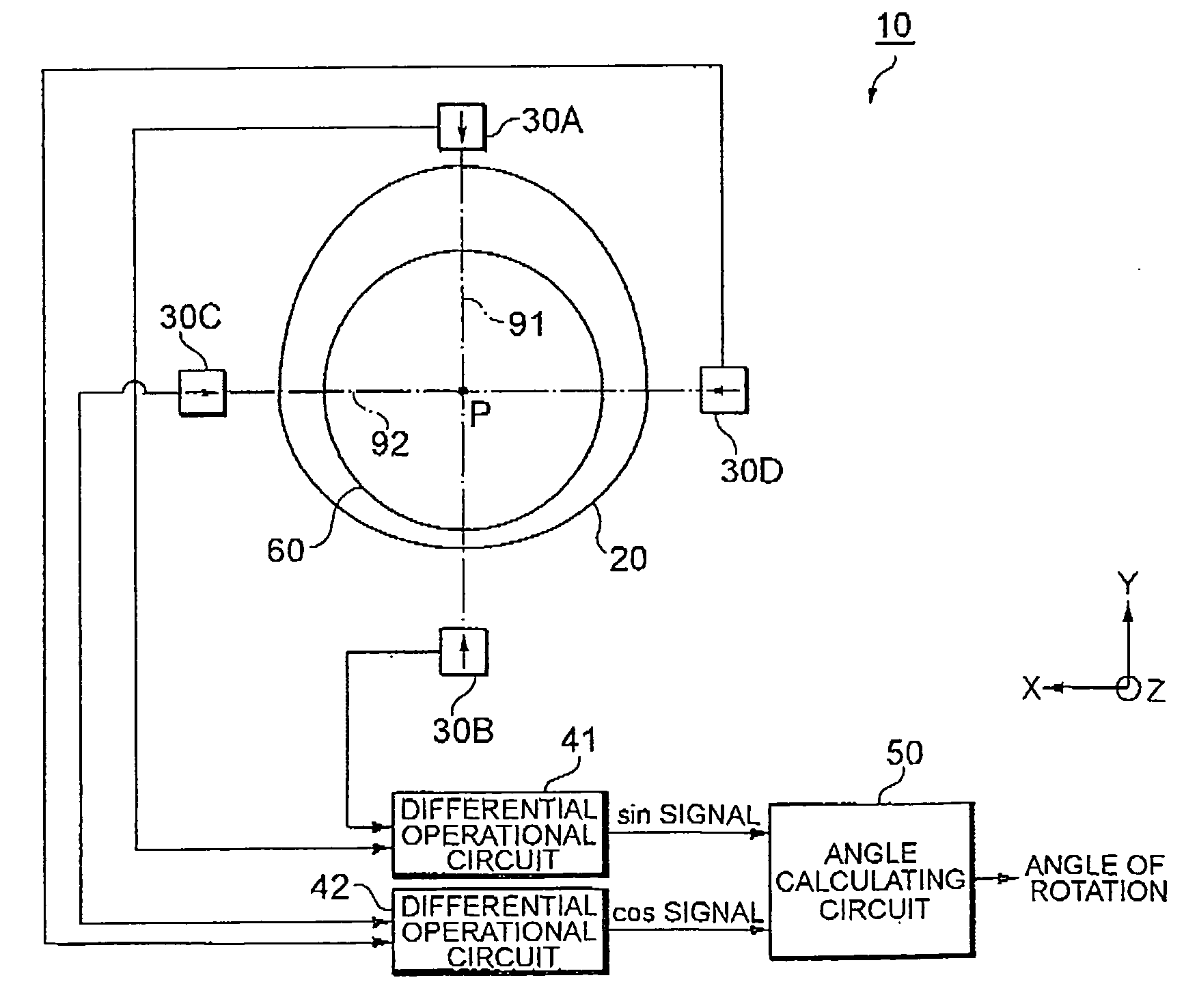
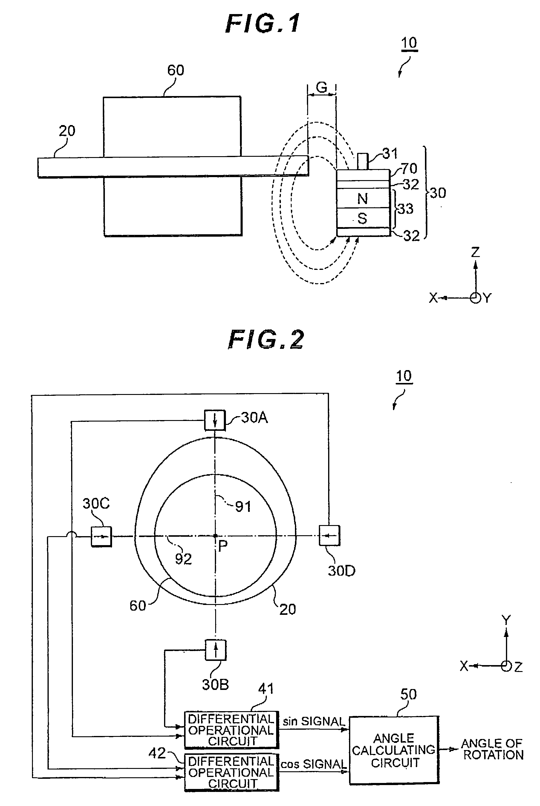
An angle detecting apparatus includes a rotor fixed to a rotating shaft, a pair of magnetic sensors arranged opposite each other so as to output a first detection signal and a second detection signal, respectively, each of which contains information on the angle of rotation of the rotor, a differential operational circuit performing differential operation on the first detection signal and the second detection signal, and an angle calculating circuit calculating the angle of rotation of the rotating shaft based on the result of the differential operation by the differential operational circuit. Here, the distance between two points where a straight line passing through the center of rotation of the rotor crosses the outer periphery of the rotor is constant.

Description

BACKGROUND OF THE INVENTION[0001]1. Field of the Invention[0002]The present invention relates to an angle detecting apparatus and an angle detecting method for calculating the angle of rotation of a rotating shaft.[0003]2. Description of the Related Art[0004]Japanese Patent Laid-Open No. 2001-91208 proposes an angle of rotation detecting apparatus as means for detecting the angle of rotation of a detection target such as a throttle valve. The angle of rotation detecting apparatus is configured such that a magnetic field is generated between a magnet and a yoke and that a magnetic detection element located in the magnetic field is displaced from the center of rotation of a rotor. Displacing the position of the magnetic detection element from the center of rotation of the rotor changes the relationship between the angle of a magnetic flux crossing the magnetic detection element and the angle of rotation of the rotor. This change can be utilized to optionally set the output property of...

Claims


Application Information

Patent Timeline
IPC IPC(8): G01B7/30
CPCG01D5/145G01D5/24452G01D5/2449G01D5/2448G01D5/24476G01D18/001
Inventor KAITA, YOSHIOMIYAMOTO, HIROKAZUKIDO, TOSHINAO
Owner TDK CORPARATION
Why Eureka
Try Eureka