Power supply device and sequencer system

a power supply device and sequencer technology, applied in capacitor testing, resistance/reactance/impedence, instruments, etc., can solve the problems of large influence on users, prolonged down time, and reduced maintenance cos

Active Publication Date: 2010-01-14
MITSUBISHI ELECTRIC CORP
View PDF7 Cites 17 Cited by
  • Summary
  • Abstract
  • Description
  • Claims
  • Application Information

AI Technical Summary

Benefits of technology

[0011]With a power supply device according to the present invention, when a first smoothing capacitor and a second smoothing capacitor provided in a smoothing unit that smoothes the rectified output of the alternating-current power are alternately connected electrically to a live line at a predetermined timing, a degradation diagnosis is performed on the smoothing capacitor that is not connected electrically to the live line. By virtue of this configuration, the power supply device is advantageous in that an online life diagnosis can be performed while ensuring the prediction accuracy of the life diagnosis.

Problems solved by technology

If a power supply device comes to an end of its life or if a power supply device is unexpectedly broken down resulting in a system down, a production line is stopped leading to a large influence on users, for example, leading to a prolonged down time.
Further, in recent years, in the market, there are ever-increasing demands from users that a life diagnosis function is provided in a power supply device, and the cost of maintenance is decreased by preventive maintenance during operation to shorten the down time.

Method used


Image

  • Power supply device and sequencer system
  • Power supply device and sequencer system
  • Power supply device and sequencer system

Examples


first embodiment

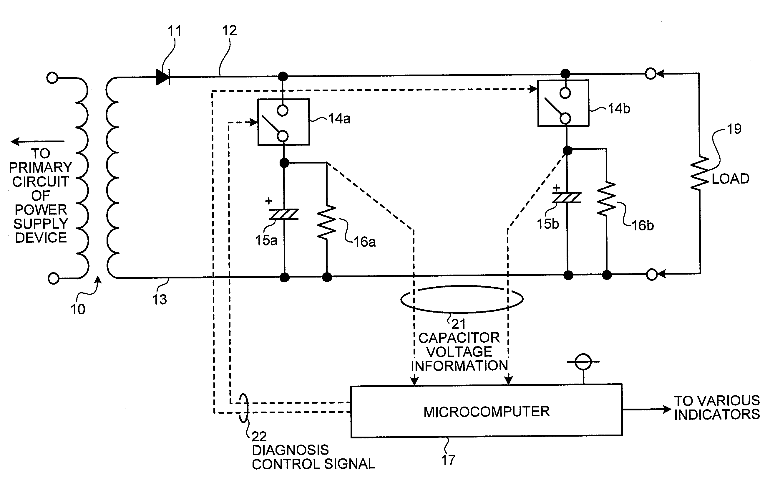
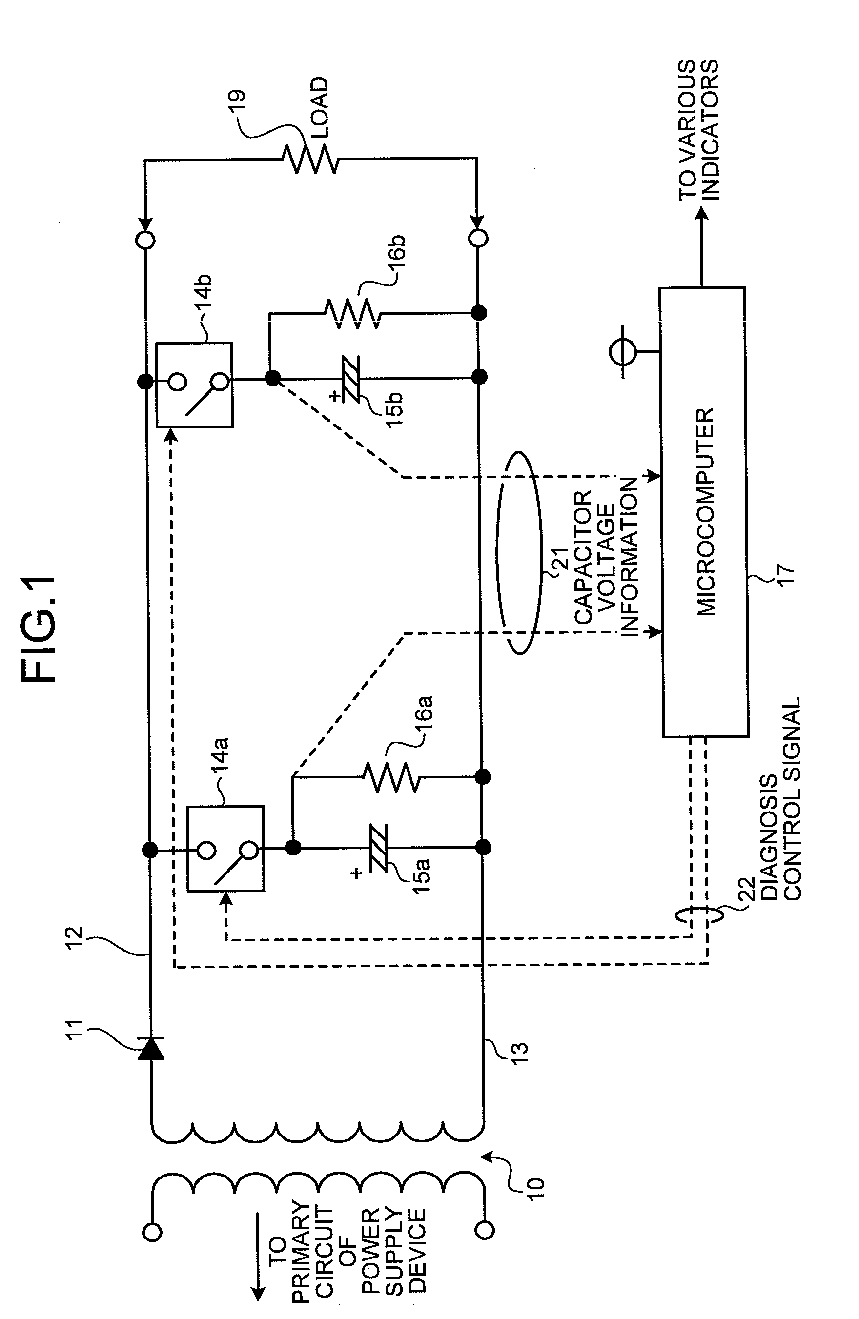
[0064]FIG. 1 is a circuit diagram showing the configuration of a power supply device according to a first embodiment of the present invention. In the embodiment, in the power supply device on its secondary side (a power supply device on a load side as viewed from a power transformer), a smoothing capacitor provided in a smoothing unit that smoothes the rectified output of the alternating-current power is duplexed, and a degradation diagnosis of the duplexed smoothing capacitor is performed, whereby an online life diagnosis of the power supply device per se can be performed.

[0065]Next, the circuit configuration of the power supply device shown in FIG. 1 will be explained. In this drawing, a transformer 10 for supplying a predetermined alternating-current power to a secondary circuit in the power supply device is provided. A diode 11 as a rectifier is inserted on a load connecting line 12 as a high-potential side live line for connecting one end of the transformer 10 to a load 19. At ...

second embodiment

[0093]FIG. 5 is a circuit diagram showing the configuration of a power supply device according to a second embodiment of the present invention. In the power supply device according to the first embodiment shown in FIG. 1, the smoothing capacitor has a duplexed configuration. On the other hand, the power supply device according to the second embodiment shown in FIG. 5 has a configuration which can cope with a requirement for the provision of three or more smoothing capacitors. Specifically, in the circuit configuration shown in FIG. 5, each of the smoothing capacitors (15a, 15b, . . . , 15k, . . . , 15p, . . . ) is inserted between a load connecting line 12 on a high-potential side and the load connecting line 13 on a low-potential side through a switching element (14a, 14b, . . . , 14k, . . . , 14p, . . . ). Further, a discharge resistor (16a, 16b, . . . , 16k, . . . , 16p, . . . ) for a life diagnosis is connected to both ends of each of the smoothing capacitors. All the smoothing ...

third embodiment

[0101]FIG. 6 is a circuit diagram showing the configuration of a power supply device according to a third embodiment of the present invention. In the power supply device according to the third embodiment shown in FIG. 6, the configuration of a startup circuit that starts and controls each switching element for electrically connecting a smoothing capacitor between load connecting lines is shown. Specifically, in the circuit configuration shown in FIG. 6, for the switching elements 14a, 14b, a startup circuit including a combination of a switching element with a capacitor and a resistor is configured. In FIG. 5 showing the configuration of the second embodiment and FIG. 6 showing the configuration of the third embodiment, identical or equivalent configurations have the same reference characters, and the overlapped description thereof will be omitted. Here only processing different from the processing in the first and the second embodiments will be explained.

[0102]In FIG. 6, a delaying...


PUM


Abstract

A smoothing unit includes a first and a second smoothing capacitors, a first and a second discharge resistors connected in parallel to both ends of the first and the second smoothing capacitors, respectively. During a normal operation, both the first and the second smoothing capacitors are connected electrically to a live line. On the other hand, during a degradation diagnosis, the first and the second smoothing capacitors are alternately connected electrically to the live line at a predetermined timing, and a smoothing capacitor not electrically connected to the live line is subjected to the degradation diagnosis.

Description

TECHNICAL FIELD[0001]The present invention relates to a power supply device, and more particularly, to a power supply device that performs a life diagnosis of a smoothing capacitor that smoothes a rectified output of an alternating-current power and a sequencer system including the power supply device.BACKGROUND ART[0002]A number of expendable components having a finite life, such as an aluminum electrolytic capacitor, have hitherto been used in a power supply device, so that the power supply device itself has been considered as a component having its set life.[0003]If a power supply device comes to an end of its life or if a power supply device is unexpectedly broken down resulting in a system down, a production line is stopped leading to a large influence on users, for example, leading to a prolonged down time.[0004]Further, in recent years, in the market, there are ever-increasing demands from users that a life diagnosis function is provided in a power supply device, and the cost...

Claims


Application Information

Patent Timeline
Patent Type & Authority Applications(United States)
IPC IPC(8): G01R27/26
CPCH02J1/14H02M7/06H02M3/06G01R31/64G01R31/00
Inventor YAMANAKA, TAKAHIKO
Owner MITSUBISHI ELECTRIC CORP
Why Eureka
Try Eureka