Hair Trimmers

a technology of hair trimmer and hair clip, which is applied in the direction of metal working apparatus, etc., can solve problems such as significant discomfort, and achieve the effects of reducing the tendency of hair to grow, ensuring comfort in the use of the trimming unit, and effective trimming results

Inactive Publication Date: 2010-01-21
THE GILLETTE CO
View PDF45 Cites 35 Cited by
  • Summary
  • Abstract
  • Description
  • Claims
  • Application Information

AI Technical Summary

Benefits of technology

[0005]The trimming unit of the invention may be assembled from few parts. It has a plastic housing on which the blade is mounted and which guides the blade over a hirsute body area in the course of trimming the hairs of this body area. The housing defines a contact surface which has a generally planar face for resting flat against and sliding over the hirsute body area in an essentially coplanar sliding contact so that the blade is maintained at a substantially constant distance or height from the level of the skin of the body area over which the housing slides, and is retained in a set orientation with respect to the skin surface. This blade orientation is forwardly inclined towards the contact surface, which helps ensure comfort in use of the trimming unit by reducing tendency for hairs to be pulled on engagement by the cutting edge of the blade. The forwardly projecting parallel elements function like the tines of a comb to separate hairs and thereby assist in guiding the hairs for engagement by the cutting edge of the blade as the hair trimming unit slides forwardly over the hirsute body area.
[0006]Although more than one blade could be included in the hair trimming unit, a single blade is preferred to avoid risk of hairs being engaged simultaneously by several blades in the course of being cut, which can be a cause of significant discomfort. The positioning of the blade edge at a distance of at least 0.5 mm, and preferably at 1.0 mm to 8.0 mm from the contact surface has been found to produce effective trimming results and to be suitable for most body areas and users.
[0007]The projecting elements of the housing are preferably uniformly spaced apart along the housing in the direction of the cutting edge. These elements can define the c

Problems solved by technology

Although more than one blade could be included in the hair trimming unit, a single blade is preferred to avoid risk of hair

Method used


Image

  • Hair Trimmers
  • Hair Trimmers
  • Hair Trimmers

Examples


Embodiment Construction

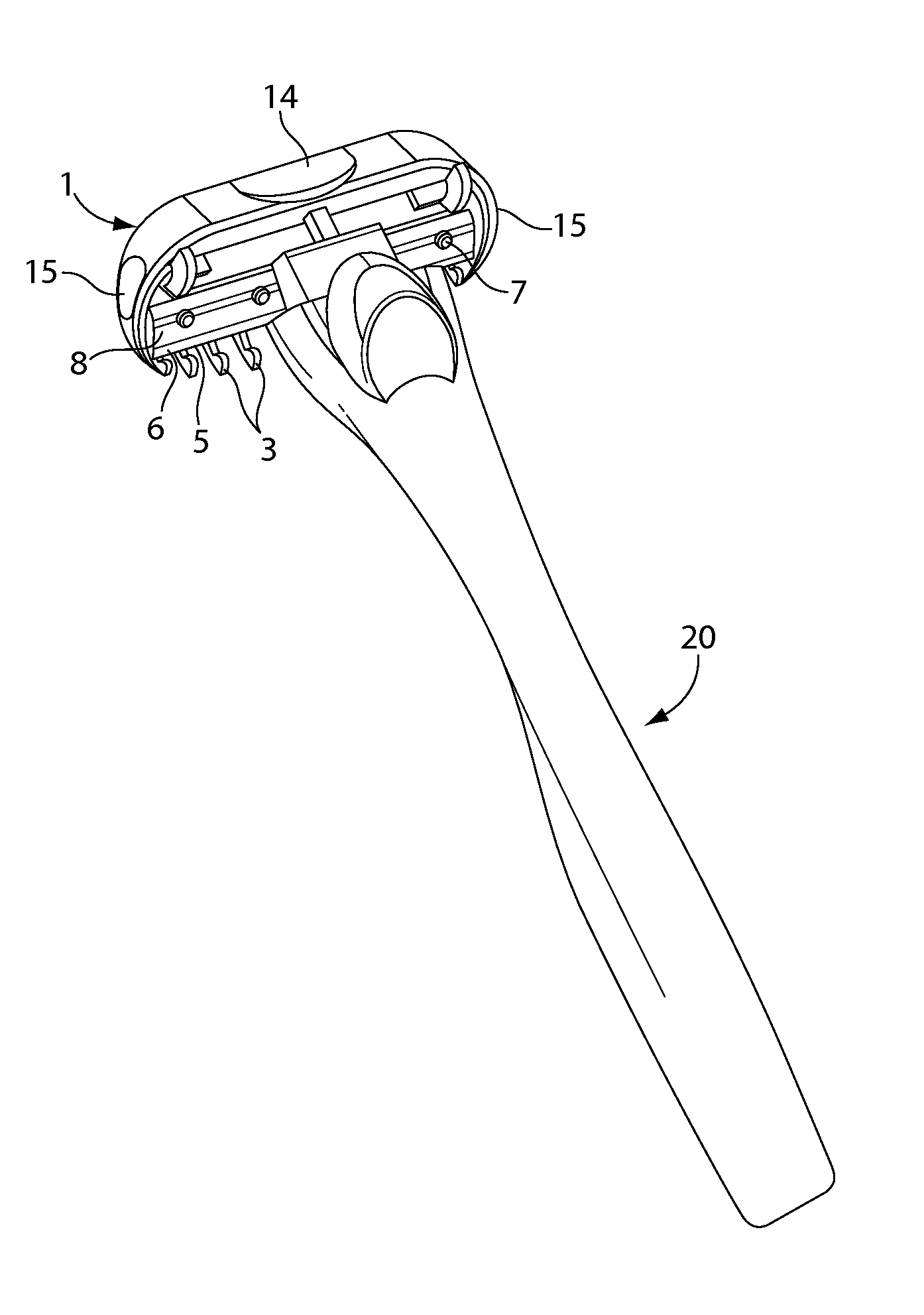
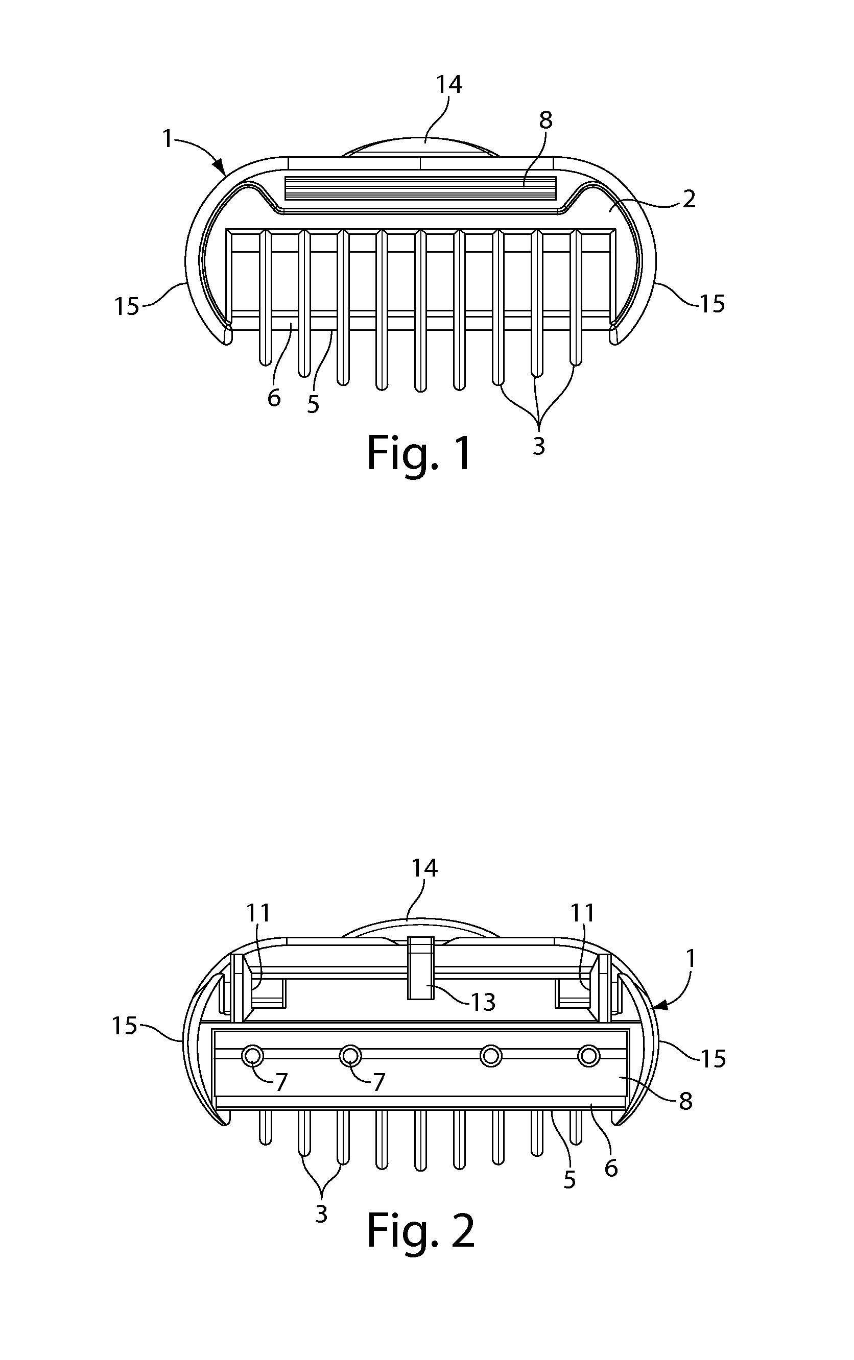
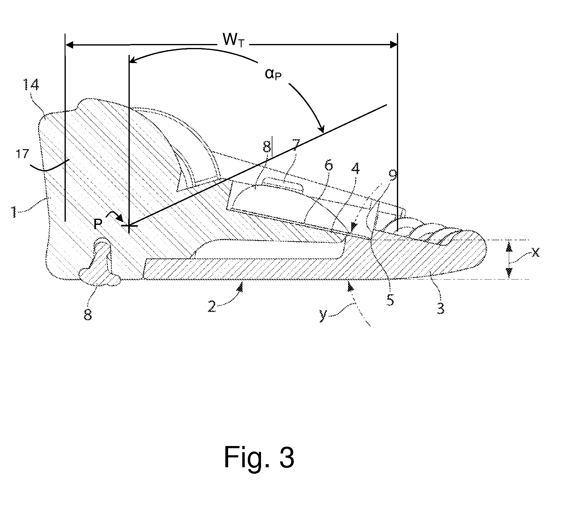
[0035]Several embodiments of hair trimming units according to the invention are shown in the drawings, and the same reference numerals are used in all the Figures to designate corresponding components and features. Illustrated in FIGS. 1 to 6 is a hair trimming unit having a plastic housing 1 forming a frame and defining a substantially planar contact surface 2 on the underside for substantially coplanar sliding contact with a hirsute body area having hairs to be trimmed to a given length. For the purposes of the present specification the surface that is intended to contact the body is referred to as the base, bottom or underside, the side opposite the contact face is referred to as the top or upper side, the front is the direction towards which the trimming unit is moved forwardly in the course of trimming hairs, and the rear is opposite the front. However, it will be understood that the trimming unit will be held in different attitudes in use depending on the area of the body havi...


PUM


Abstract

A hair trimming unit has a plastic housing 1 with a contact surface 2 for substantially flat coplanar sliding contact with a hirsute body area. A first blade 6 with a first elongate cutting edge 5 is mounted on a blade platform 4 formed on the housing so that the blade is forwardly inclined towards the contact surface and the blade edge 5 is at a set height above the contact surface. A connection member 10 is joined to the housing 1 where the member pivots about a pivot axis that is disposed at a point that is between about 10% and 70% of the trimming width as measured from the rear wall. A series of forwardly projecting elements 3 on the housing extend over the blade edge on the side of the contact surface and provide a comb structure for separating hair and guiding the hairs into contact with the exposed blade edge sections between the elements 3.

Description

CROSS REFERENCE TO RELATED APPLICATIONS[0001]This application claims the benefit of U.S. Provisional Application No. 61 / 135,095, filed Jul. 16, 2008.FIELD OF THE INVENTION[0002]This invention relates to hair trimmers, and more particularly to a hair trimming unit for trimming hair to a given length.BACKGROUND OF THE INVENTION[0003]Various forms of hair trimming devices have been proposed in the past. Whereas a razor is generally designed to remove all hair by cutting hairs as close as possible to the skin from which they protrude, hair trimmers are adapted for shortening the length of hairs while still leaving a desired length extending from the skin. Prior art hair trimmers include electric trimming devices with blades or foils which are driven to sever hairs with a shearing action, comb-like devices incorporating blades to cut hairs in the course of combing hair, and scissors. Many of the manual devices require considerable skill to obtain an even cutting of hairs to uniform lengt...

Claims


Application Information

Patent Timeline
IPC IPC(8): B26B21/40B26B19/00
CPCB26B21/42B26B21/225
Inventor NICOLL, ROYADAMS, ISABELLE JANEWATTAM, CHIRSTOPHERGOODHEAD, IAN ANTHONY
Owner THE GILLETTE CO
Why Eureka
Try Eureka