
Measuring element comprising a track used as a material measure and corresponding measurement method carried out by means of such a measuring element

a technology of measuring elements and tracks, applied in the field of measuring elements, can solve the problems of requiring additional sensor systems and requiring eight or more sensors to be able to determine the position, and achieve the effect of reducing the number of sensors and reducing the number of measurement methods

Inactive Publication Date: 2010-01-21
SIEMENS AG
View PDF9 Cites 10 Cited by
  • Summary
  • Abstract
  • Description
  • Claims
  • Application Information

AI Technical Summary

Benefits of technology

[0013]One object of the present invention lies in specifying a simple measuring element and a simple measurement method for determining a position, especially an absolute position.
[0016]The measuring element and the measurement method have the advantage that they allow the determination of the absolute position within one complete revolution or the complete range of travel of a linear axis with basically with only one individual track operating as a material measure.
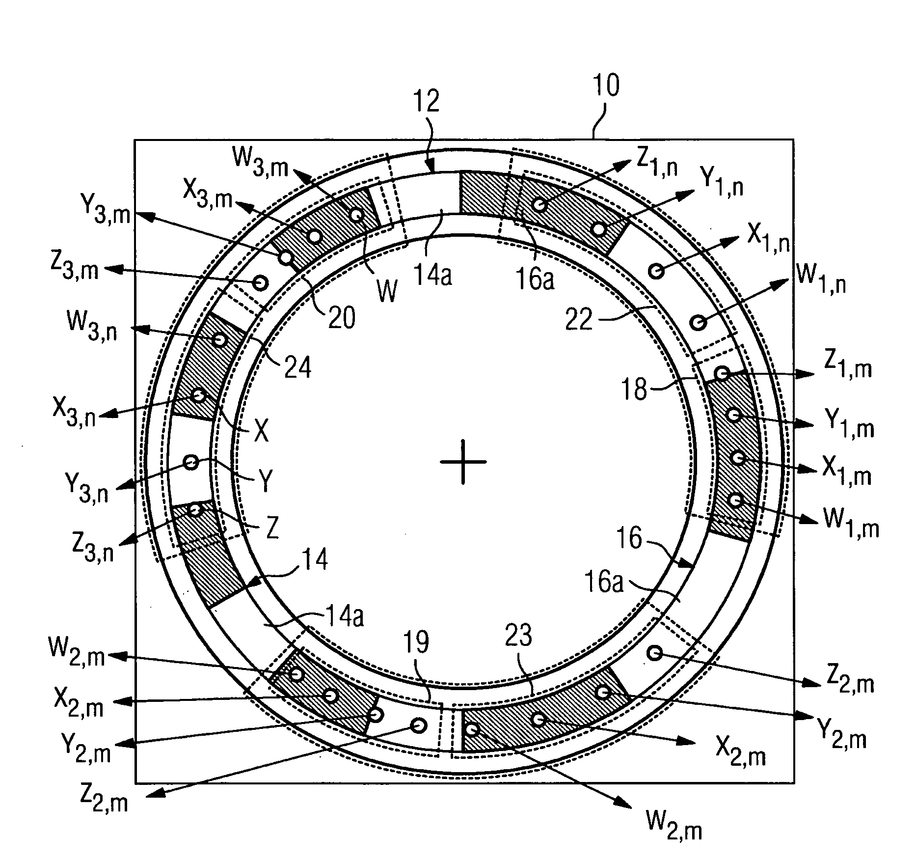
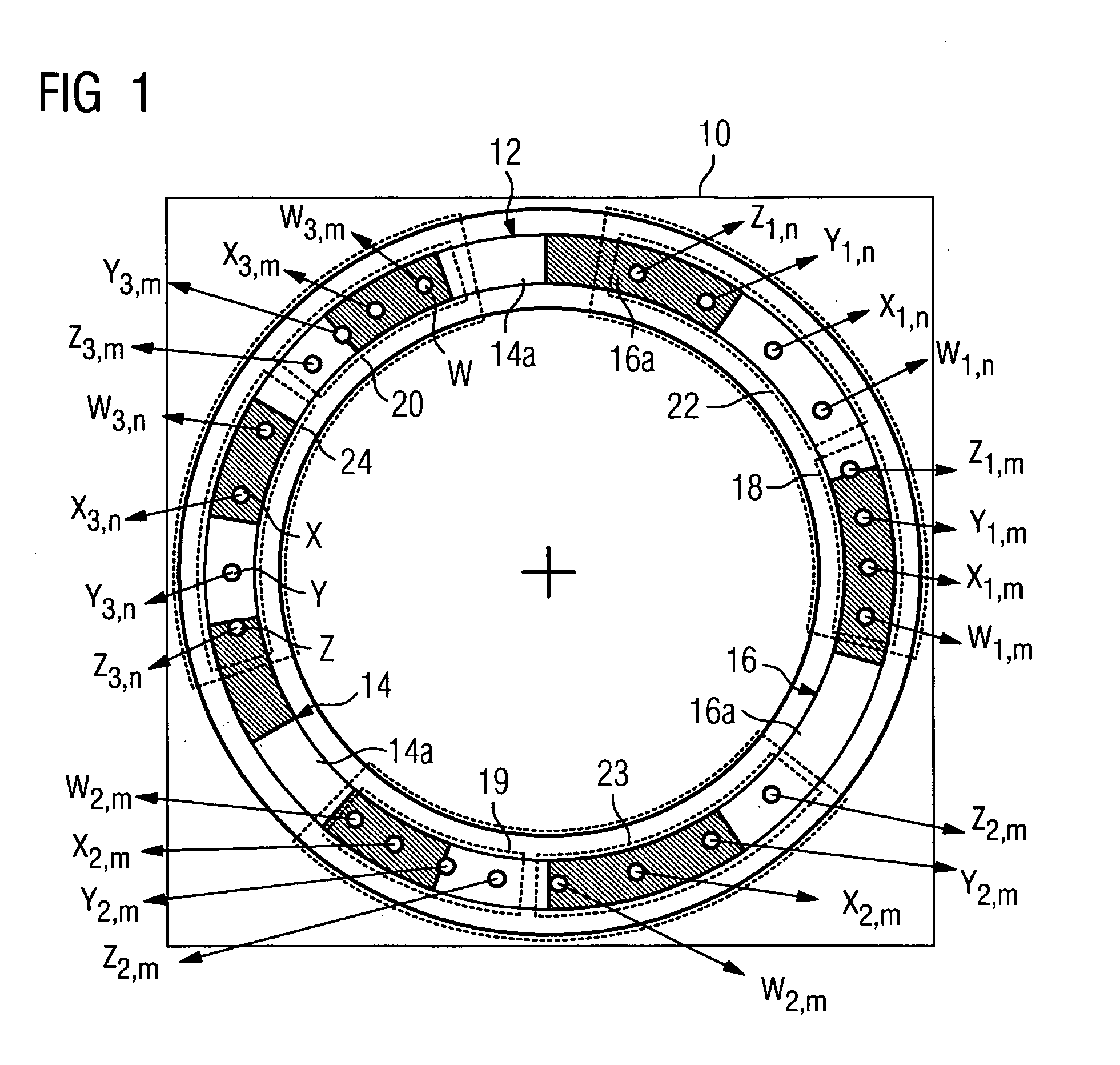
[0018]Comparatively simple mathematical relationships for determination of the absolute position are produced when the measuring element has partial tracks which are dimensioned in accordance with precisely two different grating periods and six scanning heads, of which three are matched in their sensor arrangement to the first of these grating periods and three others are matched in their sensor arrangement to the second of these grating periods.
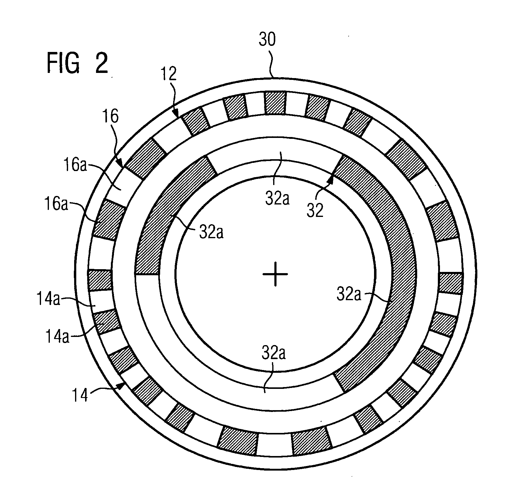
[0022]If, as well as the track, a further track is provided which is embodied as an absolute track, a precise position is also able to be determined within a smaller area, for example within one or more increments of the absolute track. Overall this allows an absolute position to be determined, in that in a first step with the aid of the absolute track a rough position and in a second step with the additional aid of the other track a more precise position is determined. In this case the invention has the advantage that the position within such an area can be determined with a greater accuracy than is possible with only one single incremental track with only one grating period. Compared to the use of two or more such incremental tracks, such as described in DE 41 23 722 A1 for example, the invention has the advantage that only one additional track is needed in addition to the absolute track.

Problems solved by technology

In this case the disadvantage arises of on the one hand additional sensor systems being needed for detecting the transitions and on the other hand of eight or more sensors usually being needed for determining the position.
European patent application 0 503 716 discloses a sensor for determining an absolute position, with an absolute track and an incremental track being combined as a material measure to form a single composite track, with the absolute track being design such that its individual increments are distributed pseudo-randomly In this case the disadvantage is that eight or more sensors are usually needed to be able to determine the position.

Method used


Image

  • Measuring element comprising a track used as a material measure and corresponding measurement method carried out by means of such a measuring element
  • Measuring element comprising a track used as a material measure and corresponding measurement method carried out by means of such a measuring element
  • Measuring element comprising a track used as a material measure and corresponding measurement method carried out by means of such a measuring element

Examples


Embodiment Construction

[0031]Measuring elements with for example two incremental tracks are generally known. Likewise known are the mathematical basics which allow, based on sensors detecting one of the tracks in each case and sensor signals related thereto, for determining a position, for circular, concentric tracks an angle of rotation φ to be detected, as a relative position relationship between the tracks and sensor / sensors. With two incremental tracks with m or n grating periods for example each incremental track is assigned a scanning head with two sensors in each case. With a similar form of rotational movement of a disk comprising such tracks, each sensor delivers a sine-wave signal, with the two signals of a scanning head in each case being phase-offset by 90°. Depending on the angle of rotation φ to be detected, this produces the following sensor signals

xm(φ)=Am·sin(mφ+γm),   (10a)

ym(φ)=Am·cos(mφ+γm),   (10b)

xn(φ)=An·sin(mφ+γn),   (10C)

xn(φ)=An·cos(mφ+γn),   (10d)

with γm and γn being constants w...


PUM


Abstract

A measuring element with a circular or linear track that encompasses a material measure and a number of sensors for scanning the track is disclosed. At least two scanning heads having the sensors are provided for scanning the track. The track of the measuring element has at least one first and a second partial track which are each provided with a first and a second grating period. For each grating period, one of the scanning heads is equipped with a sensor array that is adjusted to the grating period.

Description

CROSS REFERENCE TO RELATED APPLICATIONS[0001]This application is the US National Stage of International Application No. PCT / EP2007 / 059319 filed Sep. 6, 2007 and claims the benefit thereof. The International Application claims the benefit of German Patent Application No. 10 2006 048 628.5 DE filed Oct. 13, 2006, both of the applications are incorporated by reference herein in their entirety.FIELD OF INVENTION[0002]The invention relates to a measuring element with at least one track, with the track featuring a material measure. The invention further relates to an appropriate measurement method.BACKGROUND OF INVENTION[0003]Sensors are used for determining a position, especially an absolute position, e.g. a machine axis or the like, for example in a machine tool, production machine and / or a robot. In such cases commercially available sensors for detection of the location, i.e. the position, feature a measuring element which can be present as a linear element or as a rotational element, ...

Claims


Application Information

Patent Timeline
IPC IPC(8): G01D5/347
CPCG01D5/2492G01D5/2455
Inventor FINKLER, ROLAND
Owner SIEMENS AG
Learn More