Metal stud for a wall or roof system

a technology of metal studs and wall systems, applied in the direction of girders, joists, trusses, etc., can solve the problem of not intended summary

Active Publication Date: 2010-01-21
KESTER JEFF
View PDF10 Cites 7 Cited by
  • Summary
  • Abstract
  • Description
  • Claims
  • Application Information

AI Technical Summary

Benefits of technology

[0013]A further object of the invention is to provide a metal stud for a wall or roof system which may be fabricated to length at the factory and then installed at the job site thereby preventing wastage of material as found in the prior art methods of construction.

Problems solved by technology

Moreover, this Summary is not intended for use as an aid in determining the scope of the claimed subject matter.

Method used


Image

  • Metal stud for a wall or roof system
  • Metal stud for a wall or roof system
  • Metal stud for a wall or roof system

Examples


Embodiment Construction

[0024]Embodiments are described more fully below with reference to the accompanying figures, which form a part hereof and show, by way of illustration, specific exemplary embodiments. These embodiments are disclosed in sufficient detail to enable those skilled in the art to practice the invention. However, embodiments may be implemented in many different forms and should not be construed as being limited to the embodiments set forth herein. The following detailed description is, therefore, not to be taken in a limiting sense in that the scope of the present invention is defined only by the appended claims.

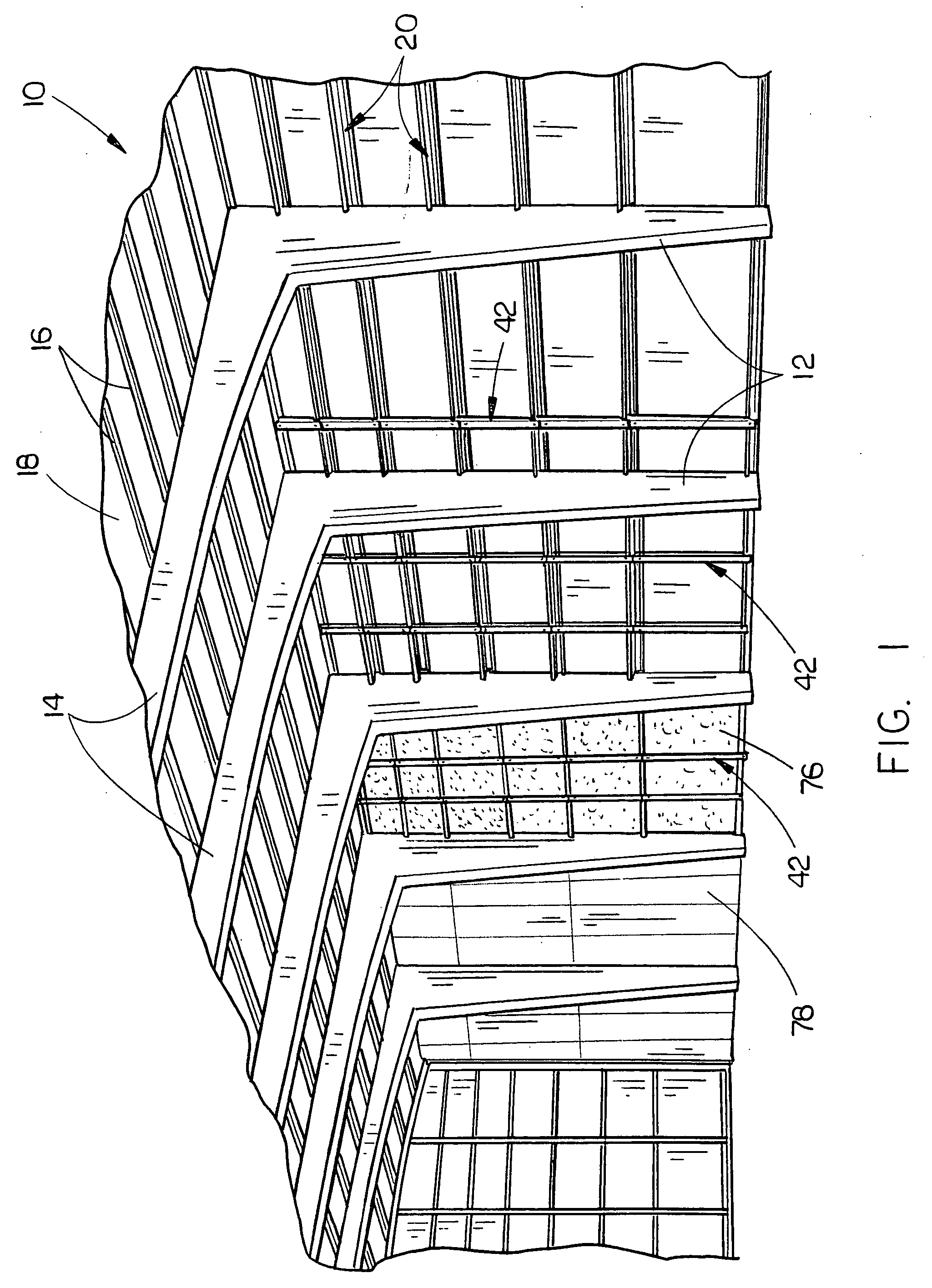
[0025]FIG. 1 illustrates a conventional steel building 10 which includes a plurality of horizontally spaced-apart columns or posts 12 having a plurality of rafter members 14 extending inwardly from the upper ends thereof which extend towards the other side of the building 10 and which are supported by similar columns or posts at the other side of the building. Rafter members 14 and...


PUM


Abstract

A metal stud for use in a metal building wherein the studs are secured to horizontally extending and vertically spaced-apart girts which are either C-shaped or Z-shaped. A metal stud is generally C-shaped and includes a base wall portion and opposite side wall portions with upper and lower ends. The lower ends of the side wall portions each have slot formed therein wherein which are adapted to receive a wall portion and flange of a girt. The upper end of the stud has a tab which extends upwardly therefrom to enable the tab to be secured to a girt. The stud may also be used in the roof system of the building.

Description

BACKGROUND OF THE INVENTION[0001]1. Field of the Invention[0002]This invention relates to a metal stud for a wall system and more particularly relates to a metal stud for use in the wall system of a metal building with the studs being positioned between and secured to horizontally extending and vertically spaced girts which are secured to and which extend between vertically disposed posts or columns. The studs of this invention may also be used in the roof system of the metal building.[0003]2. Description of the Related Art[0004]In the construction of metal buildings, a plurality of vertically disposed posts or columns are secured to a foundation and have rafter members secured to the upper ends thereof which extend across the roof of the building for supporting a roof structure thereon. A plurality of horizontally extending and vertically spaced girts are secured to the posts and extend therebetween. An exterior wall structure is normally secured to the outer sides or ends of the g...

Claims


Application Information

Patent Timeline
Patent Type & Authority Applications(United States)
IPC IPC(8): E04C3/32
CPCE04C3/07E04C2003/0421E04H5/10E04C2003/0473E04C2003/0434
Inventor KESTER, JEFF
Owner KESTER JEFF
Why Eureka
Try Eureka