Supercharge Your Innovation With Domain-Expert AI Agents!

Substrate transfer apparatus

a technology of transfer apparatus and substrate, which is applied in the direction of coating, chemical vapor deposition coating, metallic material coating process, etc., can solve the problems of not being able to achieve the positioning of the fitting and not being able to smooth the fitting

Inactive Publication Date: 2010-01-21
SHARP KK
View PDF23 Cites 0 Cited by
  • Summary
  • Abstract
  • Description
  • Claims
  • Application Information

AI Technical Summary

Benefits of technology

The present invention is a substrate transfer apparatus that aims to prevent transfer-related troubles. It includes multiple floating-transfer guide plates with gas ejecting holes, a gas supplying source, a tray for mounting a substrate, and a transfer arm for transferring the tray to another guide plate. The tray has a main body portion and an outward projecting portion, and the transfer arm is in contact with the outward projecting portion during transfer. The technical effect of this invention is to provide a reliable and efficient substrate transfer system.

Problems solved by technology

However, there arise problems described below in the substrate transfer apparatus, of the substrate transfer apparatuses having the transfer arm and the transfer drive unit, in which the substrate is not directly mounted on the guide plate, but the substrate is mounted through a tray placed on the guide plate in order to protect the surface of the substrate.
When the tray and the transfer arm are configured as described above, it is not so easy to achieve positioning of the fitting holes on the tray and the leading portion of the transfer arm upon the fitting.
This provides non-smooth fitting, which entails a trouble related to the transfer.
When the tray and the transfer arm are configured as described above, and further, the guide plate has incorporated therein a heater for heating the substrate, wherein the heater is formed to have the width almost the same as that of the substrate, the problem described below arises.
Due to the difference in the temperature distribution, the tray might be curved upwardly at the portion close to the side edge, which entails a trouble related to the transfer.

Method used


Image

  • Substrate transfer apparatus
  • Substrate transfer apparatus
  • Substrate transfer apparatus

Examples


first embodiment

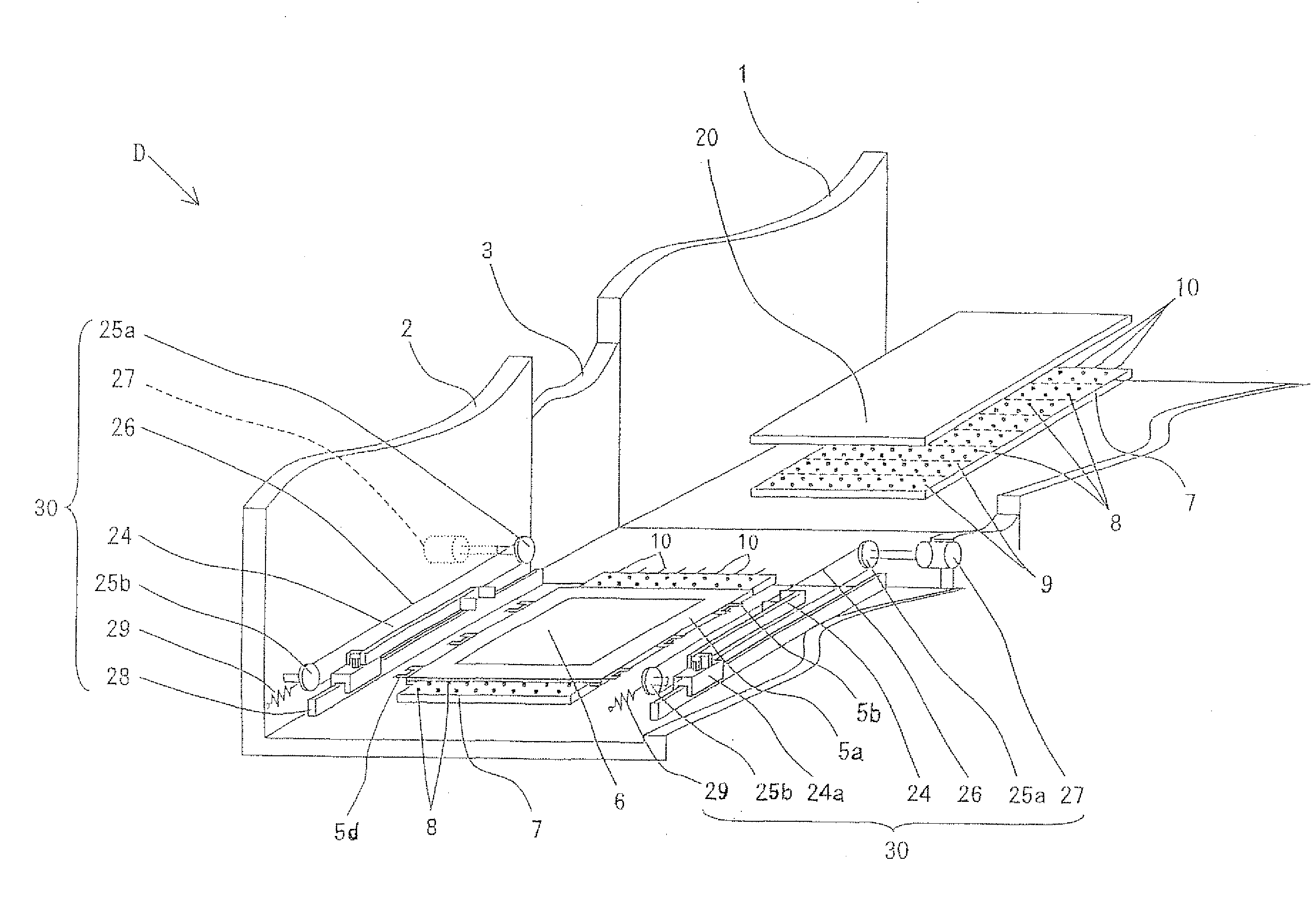
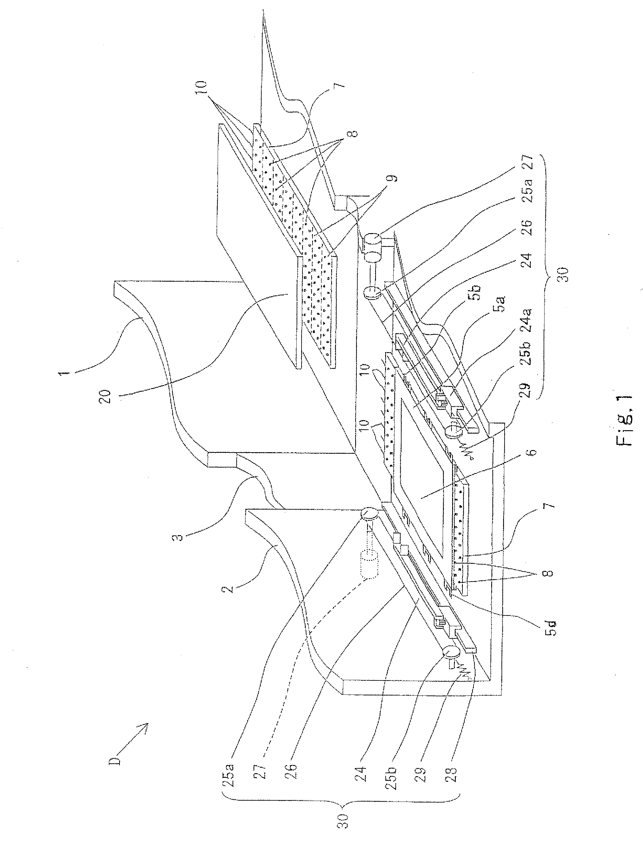
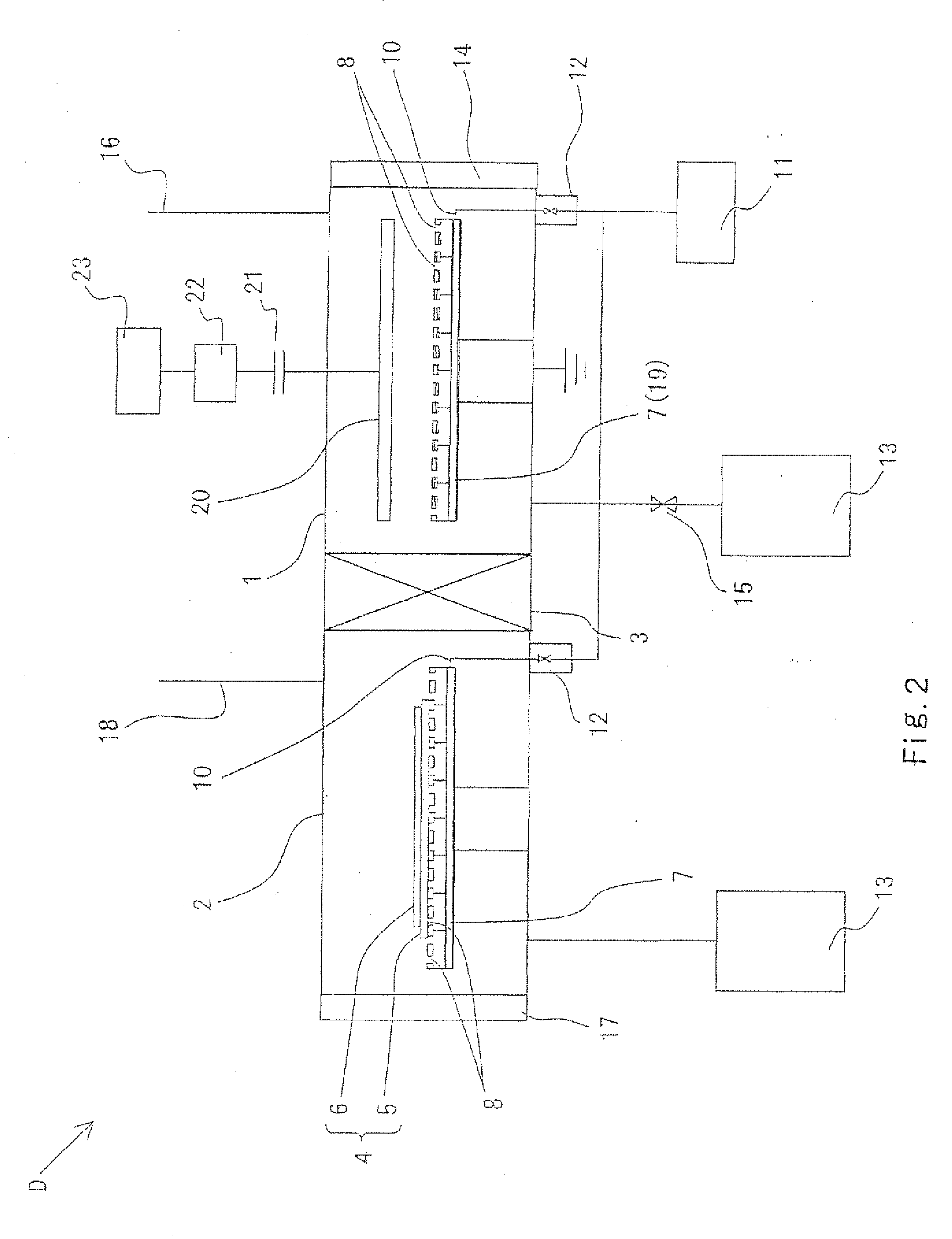
[0068]FIG. 1 is a partially cutout perspective view of a substrate transfer apparatus, which is incorporated in a plasma processing apparatus, according to a first embodiment of the present invention. FIG. 2 is a view for explaining the configuration of the substrate transfer apparatus shown in FIG. 1. FIG. 3 is a plan view of a tray, which is one component in the substrate transfer apparatus shown in FIG. 1. FIG. 4 is a plan view of a transfer arm, which is another component in the substrate transfer apparatus shown in FIG. 1.

[0069]As shown in FIGS. 1 and 2, the substrate transfer apparatus D according to the first embodiment of the present invention is incorporated in a plasma processing apparatus. The substrate transfer apparatus D has a first vacuum chamber 1 and a second vacuum chamber 2 that are adjacent to each other with a space from the upstream side to the downstream side in a transfer direction. These two vacuum chambers 1 and 2 are configured such that one casing linearl...

second embodiment

Modifications of Second Embodiment

[0112]FIGS. 7 to 9 respectively show inward projecting ends 24h, 24i, and 24j (modifications 1 to 3) provided to the free end of the arm portion 24c in the substrate transfer apparatus according to the second embodiment instead of the inward projecting end 24g.

[0113]The inward projecting end 24h at an arm portion 24c in a first modification shown in FIG. 7 has an L-shaped planar shape. The inward projecting end 24i at the arm portion 24c in the second modification shown in FIG. 8 is made of a hollow tube having a rectangular-frame like front shape and rectangular planar shape. The inward projecting end 24j at the arm portion 24c in the third modification shown in FIG. 9 is formed into a laid H viewed from the front and has a rectangular planar shape.

Third Embodiment

[0114]FIG. 10 is a partially cutout perspective view showing a substrate transfer apparatus, which is incorporated in a plasma processing apparatus, according to a third embodiment of th...

third embodiment

Modifications of Third Embodiment

[0129]FIGS. 10 and 13 respectively show first to third projecting portions 45f, 45g, 45h; 45i, 45j, 45k (modifications 1 and 2) that are formed instead of the projecting portions 45b, . . . 45d of the tray 45 in the substrate transfer apparatus E according to the third embodiment.

[0130]These projecting portions 45f, 45g, 45h; 45i, 45j, 45k respectively have a base-side edge portion communicate with one side edge of the main body portion 45a, a projecting-side edge portion extending so as to be parallel to the baseside edge portion with a space, and two projecting end portions that communicate these edge portions.

[0131]Specifically, the first to third projecting portions 45f, 45g, and 45h of the tray 45 in the first modification shown in FIG. 12 has a rectangular planar shape, wherein the length of the base-side edge portion is longer than the length of the projecting end portion.

[0132]The first to third projecting portions 45i, 45j, and 45k of the tr...


PUM

PropertyMeasurementUnit
thicknessaaaaaaaaaa
thicknessaaaaaaaaaa
thicknessaaaaaaaaaa

Abstract

A substrate transfer apparatus comprising: a plurality of floating-transfer guide plates adjacent to each other with a space, each of guide plate having a plurality of floating gas ejecting holes; a gas supplying source for supplying a floating gas to the guide plates; a tray that is placed on one of the guide plates in order to mount a substrate to be transferred, and that is floated by the floating gas; and a transfer arm for transferring the floated tray to the adjacent other guide plate from the guide plate, wherein the tray includes a main body portion having both side edges parallel to a transfer direction of the tray, and an outward projecting portion that is formed so as to partially project outwardly from at least one of both side edges of the main body portion, and wherein the transfer arm is in contact and engaged with the outward projecting portion when the tray is transferred by the transfer arm.

Description

CROSS-REFERENCE TO RELATED APPLICATION[0001]This application is related to Japanese patent application No. 2008-184831 filed on Jul. 16, 2008 whose priority is claimed under 35 USC §119, the disclosure of which is incorporated by reference in its entirety.BACKGROUND OF THE INVENTION[0002]1. Field of the Invention[0003]The present invention relates to a substrate transfer apparatus, and more particularly to a substrate transfer apparatus that transfers a substrate in order to perform, for example, a plasma process onto a surface of the substrate, which is a plate-like subject to be processed having a flat plate shape.[0004]2. Description of the Related Art[0005]When a semiconductor thin film is formed on a surface of a substrate that is a subject to be processed having a flat plate shape, a plasma processing apparatus employing a plurality of vacuum chambers has widely been used. In the plasma processing apparatus described above, at least one of the plurality of vacuum chambers is g...

Claims


Application Information

Patent Timeline
Patent Type & Authority Applications(United States)
IPC IPC(8): C23C16/54C23C16/513
CPCH01L21/67784
Inventor KISHIMOTO, KATSUSHIFUKUOKA, YUSUKETOYODA, MITSUHIROTADOKORO, HIROYUKIOZAKI, YUSUKE
Owner SHARP KK
Features
  • R&D
  • Intellectual Property
  • Life Sciences
  • Materials
  • Tech Scout
  • Unparalleled Data Quality
  • Higher Quality Content
  • 60% Fewer Hallucinations
Learn More