Trap apparatus, exhaust system and processing system using same

a technology of trap apparatus and processing system, which is applied in the direction of refrigeration machines, liquefaction machines, machines/engines, etc., can solve the problems of exhaust gas or cleaning water leaking from a sliding portion, and the insufficient regeneration of the trap elemen

Inactive Publication Date: 2010-01-21
TOKYO ELECTRON LTD
View PDF4 Cites 45 Cited by
  • Summary
  • Abstract
  • Description
  • Claims
  • Application Information

AI Technical Summary

Benefits of technology

[0010]The present invention provides a trap apparatus capable of sufficiently removing an exhaust adhered to a trap element, thus enabling a successful regeneration of the trap element.
[0011]The present invention further provides a trap apparatus capable of preventing, even in case it has more than one trap element, a leakage of an exhaust gas or the like when the trap elements are switched.

Problems solved by technology

In the above-described configuration in which the trap element is cleaned just by pouring the cleaning water, the exhaust adhered to the trap element may not be sufficiently removed, resulting in a failure to regenerate the trap element sufficiently.
Thus, when the trap elements make sliding motions, the exhaust gas or the cleaning water may leak from a sliding portion, even if a sealing member is provided at the sliding portion.

Method used


Image

  • Trap apparatus, exhaust system and processing system using same
  • Trap apparatus, exhaust system and processing system using same
  • Trap apparatus, exhaust system and processing system using same

Examples


first embodiment

Configuration of the Exhaust System in Accordance with a First Embodiment

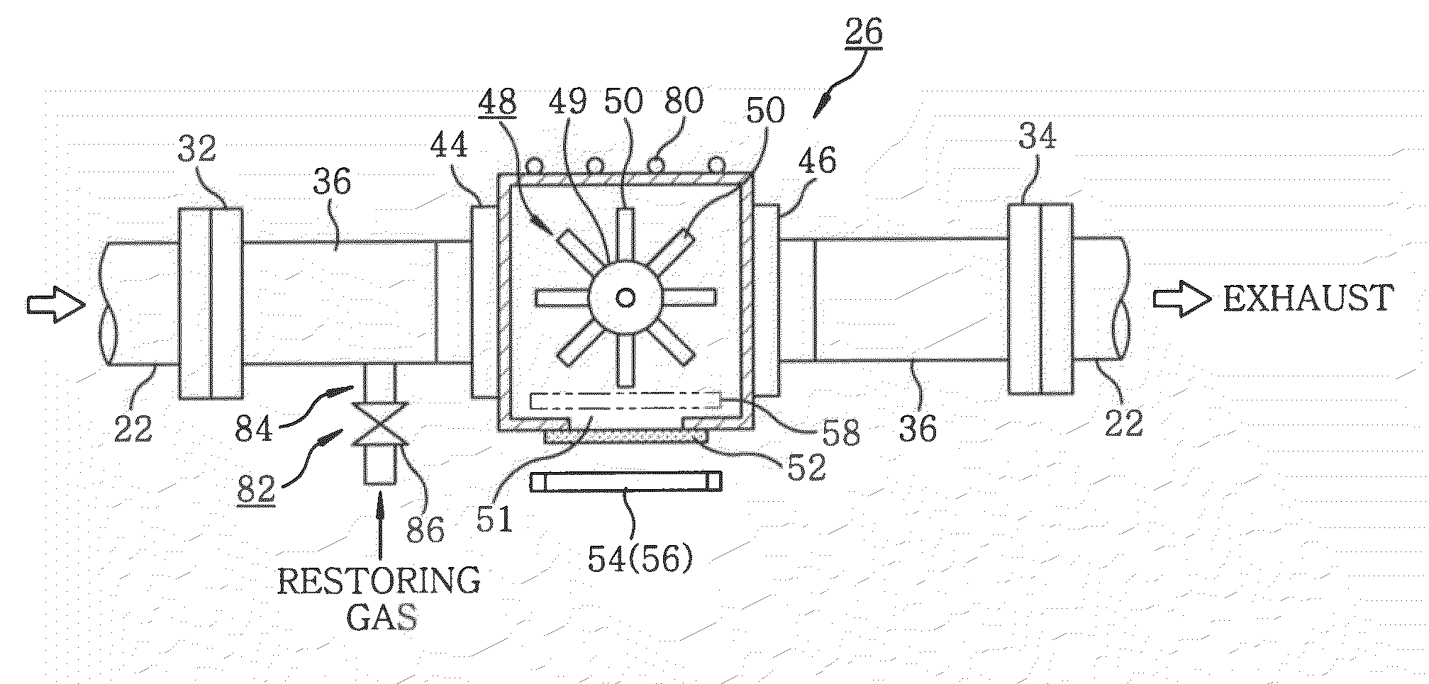
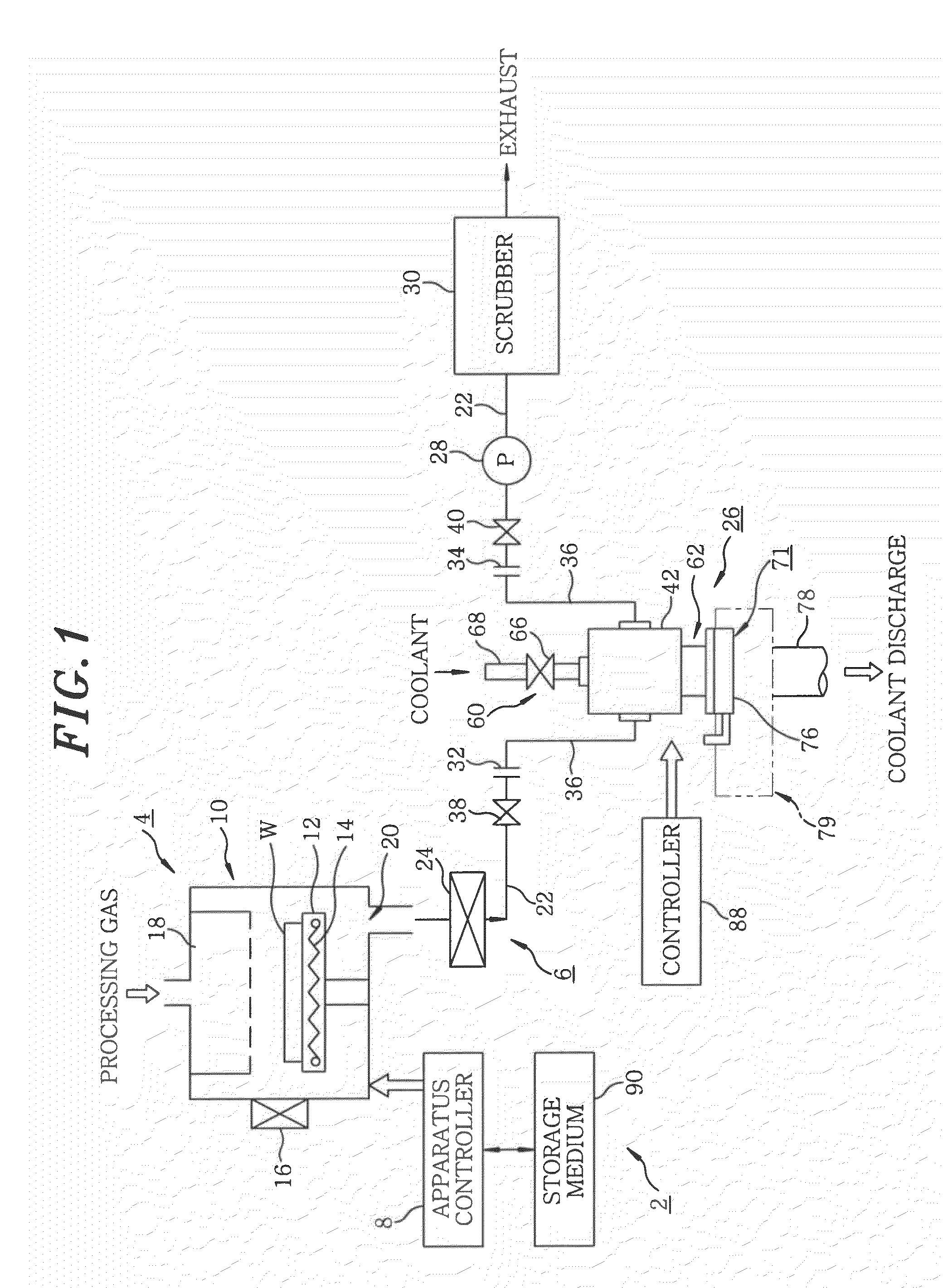
[0038]Now, the exhaust system 6 in accordance with the first embodiment will be explained. The exhaust system 6 of the first embodiment includes an exhaust passage 22 connected to the exhaust port 20 of the processing chamber 10, and the atmosphere within the processing chamber 10 can be exhausted as an exhaust gas. The exhaust gas contains gaseous exhaust such as an unreacted residual gas and a reaction by-product generated when the wafer W is processed.

[0039]Installed on the exhaust passage 22 in sequence from the upstream side are a pressure control valve 24 having a passage blocking function and a valve-opening controlling function; a trap apparatus 26 for capturing and trapping the exhaust in the exhaust gas; an exhaust pump 28 for suctioning the atmosphere within the processing chamber 10; and an exhaust gas abatement equipment 30 for removing harmful substances in the exhaust gas that have passed through...

second embodiment

Explanation of an Exhaust System in Accordance with a Second Embodiment

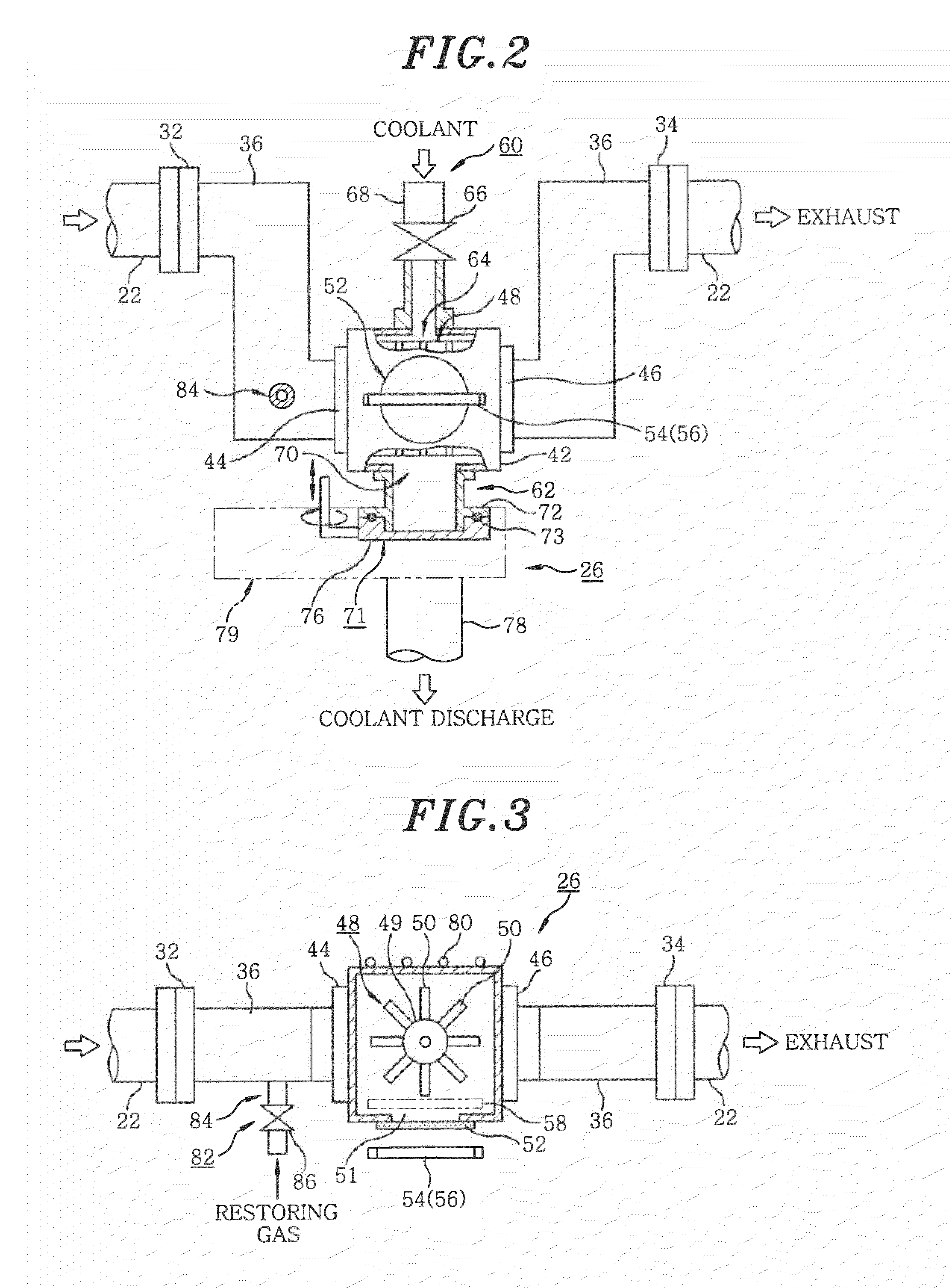
[0071]Below, an exhaust system in accordance with a second embodiment of the present invention will be explained. FIG. 7 is a partial cross-sectional top view of trap apparatuses installed in the exhaust system in accordance with the second embodiment of the present invention. Throughout FIGS. 2 and 3, like reference numerals are used for like or corresponding parts, and redundant description thereof will be omitted. Since a side view of each trap apparatus is substantially same as that shown in FIG. 2, illustration thereof will be omitted herein.

[0072]In the exhaust system of the second embodiment, plural, e.g., two trap apparatuses in this example can be installed. The two trap apparatuses are switched such that exhaust is trapped by one trap apparatus while a regenerating process is being performed on a trap element 48 of the other trap apparatus. Thus, a consecutive operation of the processing system is enabl...


PUM

PropertyMeasurementUnit
temperatureaaaaaaaaaa
transparentaaaaaaaaaa
adhesionaaaaaaaaaa

Abstract

Provided is a trap apparatus, disposed in an exhaust passage 22 for discharging an exhaust gas from a processing chamber 10 for processing a wafer W, thereby to trap exhaust from the exhaust gas, so that the exhaust trapped by a trap element can be efficiently removed to regenerate the trap element. The trap apparatus includes a housing 42 disposed in the exhaust passage, a trap element 48 disposed in the housing for trapping the exhaust, a trap heating unit 54 for heating the trap element, a coolant introducing unit 60 for introducing a coolant into the housing, a coolant discharging unit 62 for discharging the coolant from the housing, and a controller 88 which performs a control to introduce the coolant from the coolant introducing unit into the housing, while the trap element being heated by the trap heating unit, to remove the exhaust trapped by the trap element.

Description

[0001]This application is a Continuation Application of PCT International Application No. PCT / JP2008 / 055678 filed on Mar. 26, 2008, which designated the United States.FIELD OF THE INVENTION[0002]The present invention relates to a trap apparatus for capturing (trapping) exhaust in an exhaust gas from a processing apparatus which performs, e.g., a film forming process on a semiconductor wafer or the like to manufacture a semiconductor device. More specifically, the present invention relates to a trap apparatus capable of regenerating a trap element by removing the exhaust adhered to the trap element when necessary. Moreover, the present invention also relates to a processing system and an exhaust system including the trap apparatus.BACKGROUND OF THE INVENTION[0003]In general, a trap apparatus is installed in an exhaust passage for exhausting an internal atmosphere in a processing apparatus which performs a preset process such as a film forming process on a semiconductor wafer or the l...

Claims


Application Information

Patent Timeline
Patent Type & Authority Applications(United States)
IPC IPC(8): F25B29/00B01D5/00B01D8/00
CPCB01D2258/0216H01L21/67017C23C16/4412B01D53/34
Inventor YAMAZAKI, RYOJI
Owner TOKYO ELECTRON LTD
Why Eureka
Try Eureka