Caliper mounting arrangement

a mounting arrangement and caliper technology, applied in the direction of axially engaging brakes, brake types, braking elements, etc., can solve the problems of rotor cracking, bolts to bend, thermal distortion of rotors, etc., and achieve the effect of convenient access and maneuverability

Inactive Publication Date: 2010-01-21
PERFORMANCE FRICTION
View PDF9 Cites 25 Cited by
  • Summary
  • Abstract
  • Description
  • Claims
  • Application Information

AI Technical Summary

Benefits of technology

[0011]A further aspect of embodiments of the invention is to provide a caliper mounting arrangement that is easy to access and maneuver to aid in removal and reinstallation for service.

Problems solved by technology

In this type of arrangement, the shear force is transferred through the bolts, which can cause the bolts to bend, even when large bolts are used.
Bending of a bolt causes the caliper to twist, which results in many problems.
A twisted caliper can cause uneven brake pad wear and uneven rotor wear, which can lead to thermal distortion of the rotor, cracking of the rotor and premature failure of the rotor.
Twisting of the caliper can also lead to increased fluid displacement that can cause long pedal phenomenon in which a brake operator experiences a lengthened brake stroke and can also lead to a longer stopping distance.
Twisting can also cause the piston carried by the caliper that actuates movement of the brake pads to become lodged in the piston bore.
Additionally, when the caliper needs to be removed and reinstalled, it is difficult to access and manipulate the large bolts needed to withstand the shear forces.

Method used


Image

  • Caliper mounting arrangement
  • Caliper mounting arrangement
  • Caliper mounting arrangement

Examples


Embodiment Construction

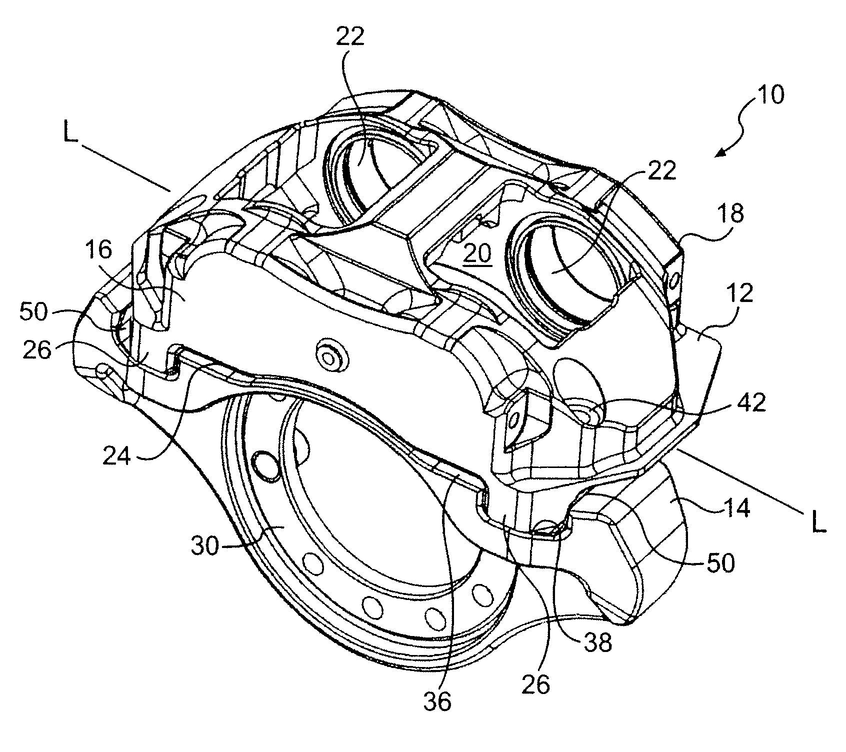
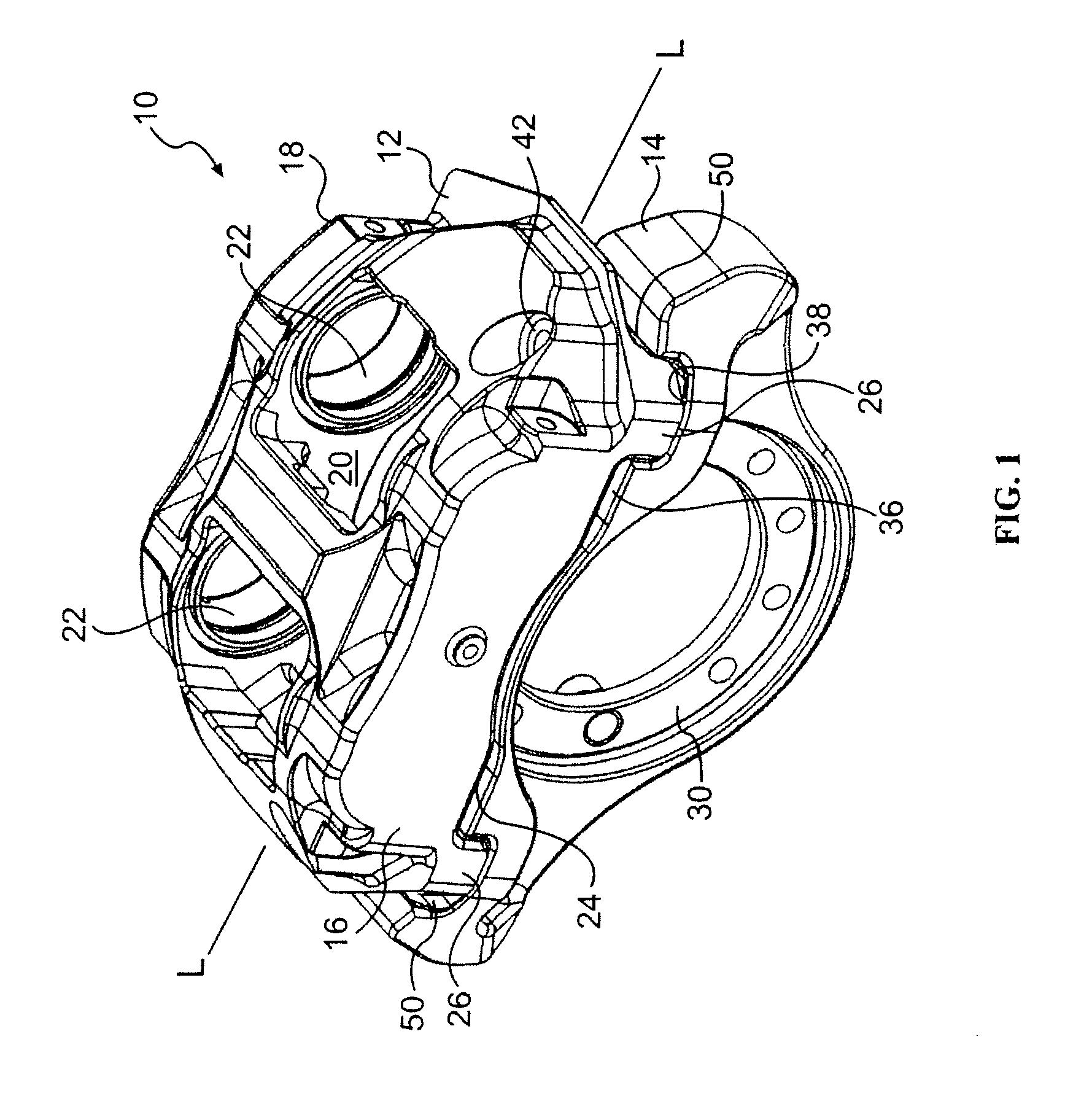
[0034]This invention is described for use in a vehicular disc brake system. The caliper assembly described below is used for illustrative purposes only and it will be understood that this invention may be used in various types of braking systems and with any rotor. The invention can be used in conventional automobiles, racing vehicles, motorcycles, medium duty vehicles, and heavy duty trucks. As the invention provides an increased ability to withstand high torque applications, it is well suited for vehicles having a gross vehicle weight (GVW) of 11,000 pounds or more, such as in trucks, ambulances, and buses. In the description below, the brake pads, rotor, and fixed mounting member are not shown as they are conventionally known.

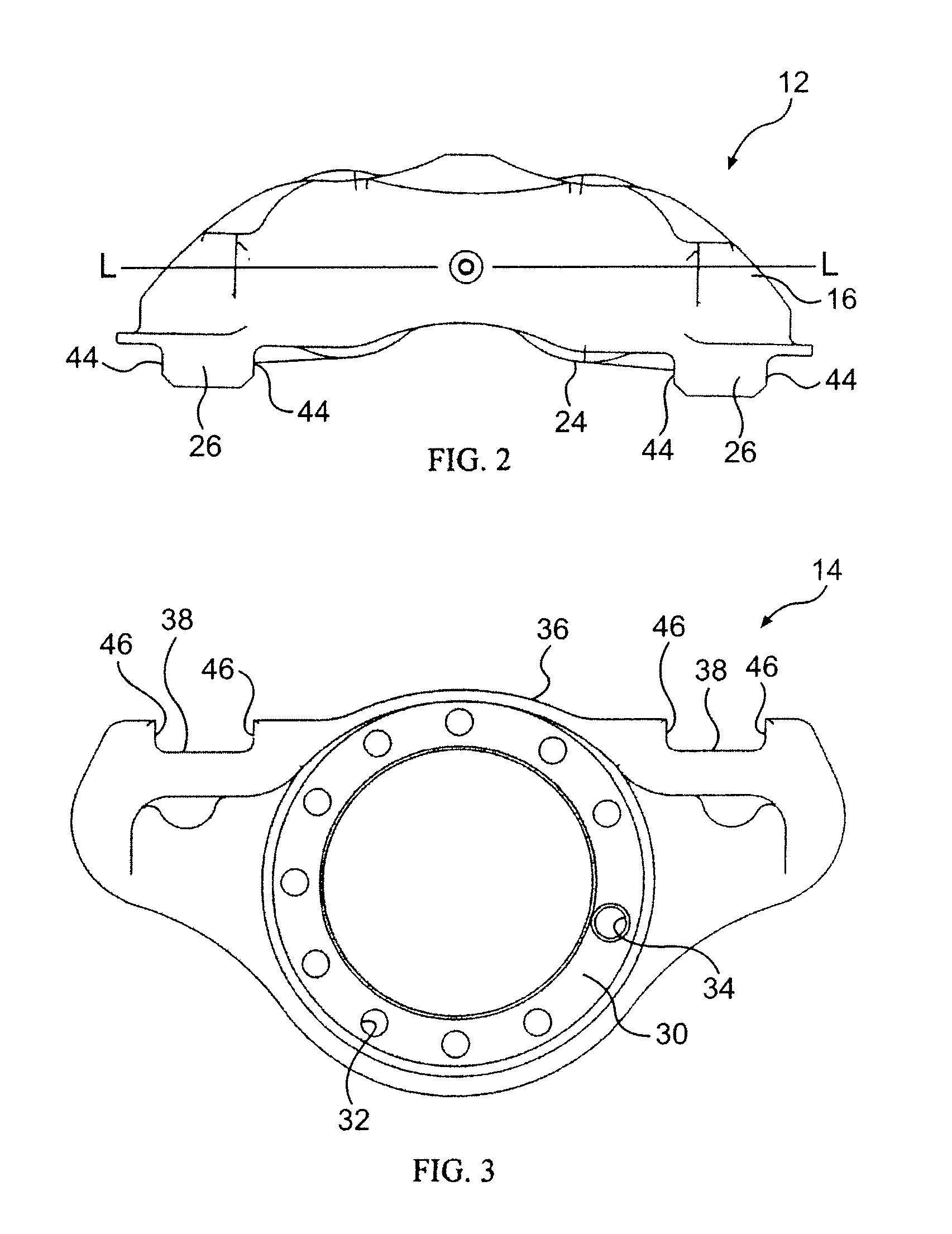
[0035]Referring to FIGS. 15-17, conventional caliper assemblies use a bolted connection between the caliper body 100 and the torque plate. The caliper body 100 includes two opposed side portions 102 and 104 that extend on either side of a longitudinal axis L...


PUM


Abstract

A brake caliper assembly includes a caliper body connected to a torque plate via a mating protrusion and cavity that transfer torque through facing abutment surfaces to reduce twisting of the caliper. The mating protrusion and cavity provide a stiff connection and also allow use of a smaller, lighter connecting bolt. This arrangement eases removal and reinstallation of the caliper.

Description

RELATED APPLICATIONS[0001]This application is a continuation of U.S. patent application Ser. No. 11 / 536,252 filed Sep. 28, 2006, which claims priority from U.S. Provisional Application No. 60 / 752,720 filed Dec. 21, 2005, the contents of both which are incorporated herein by reference.BACKGROUND OF THE INVENTION[0002]1. Field of the Invention[0003]This invention relates to brake calipers for use with disc brakes. In particular, this invention relates to the mounting arrangement of brake calipers to a vehicle support element.[0004]2. Discussion of Related Art[0005]In typical disc brake assemblies, a rotor is mounted on a wheel hub for rotation. One or more pairs of brake pads, generally designed as friction material carried on a backing plate, are supported on either side of the rotor by a caliper or an anchor bracket. Calipers are designed to apply the braking force by moving a piston relative to the rotor to thereby move the brake pad into and out of contact with the rotor. The pist...

Claims


Application Information

Patent Timeline
Patent Type & Authority Applications(United States)
IPC IPC(8): F16D65/14
CPCF16D55/228F16D2055/0016F16D2055/0008
Inventor PAUL, SCOTT ANDREWBURGOON, DONALD LEE
Owner PERFORMANCE FRICTION
Why Eureka
Try Eureka