Image reading device and image forming apparatus
- Summary
- Abstract
- Description
- Claims
- Application Information
AI Technical Summary
Benefits of technology
Problems solved by technology
Method used
Image
Examples
Example
[0023]First, a first embodiment of the present invention is described with reference to FIGS. 1 to 6.
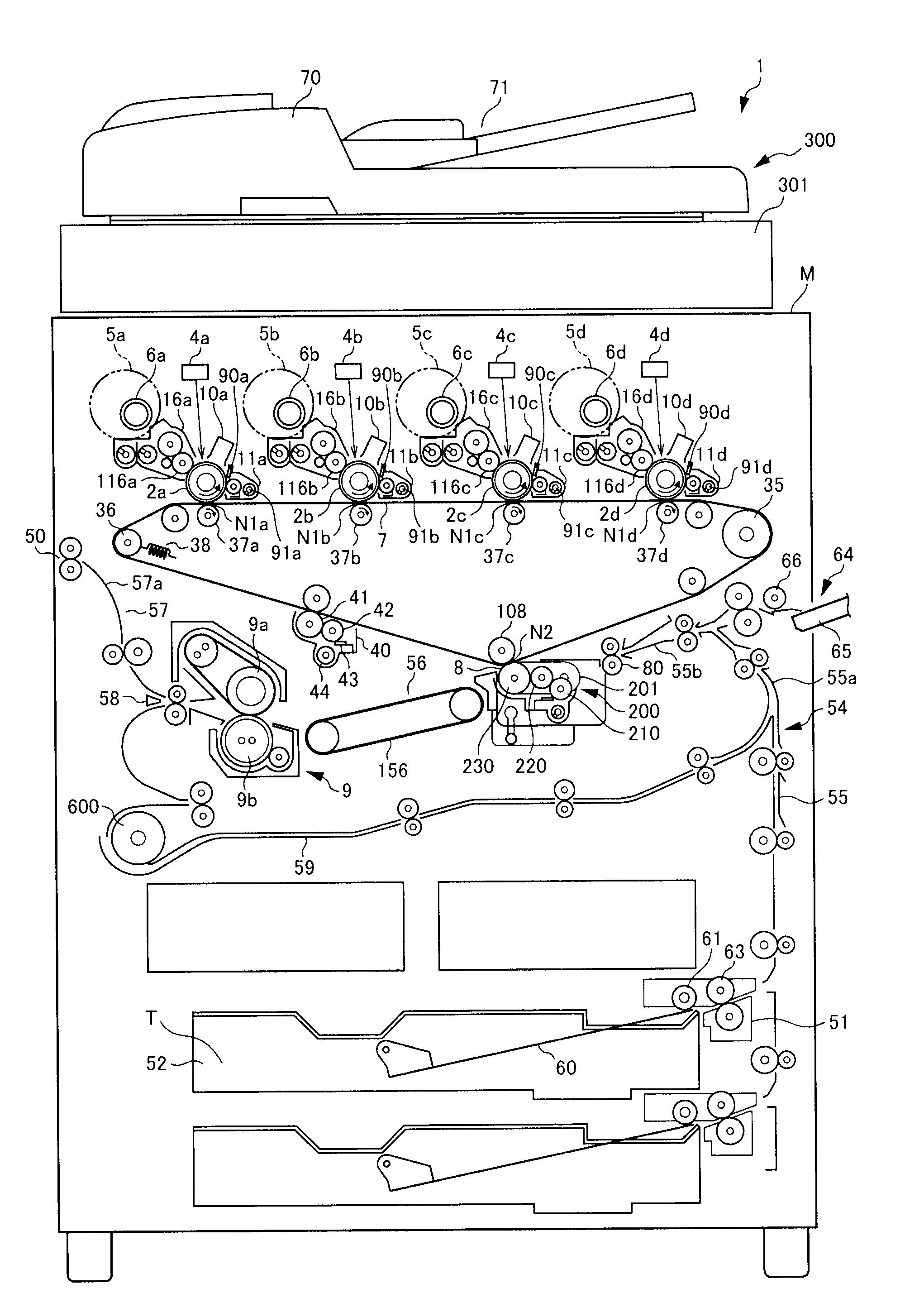
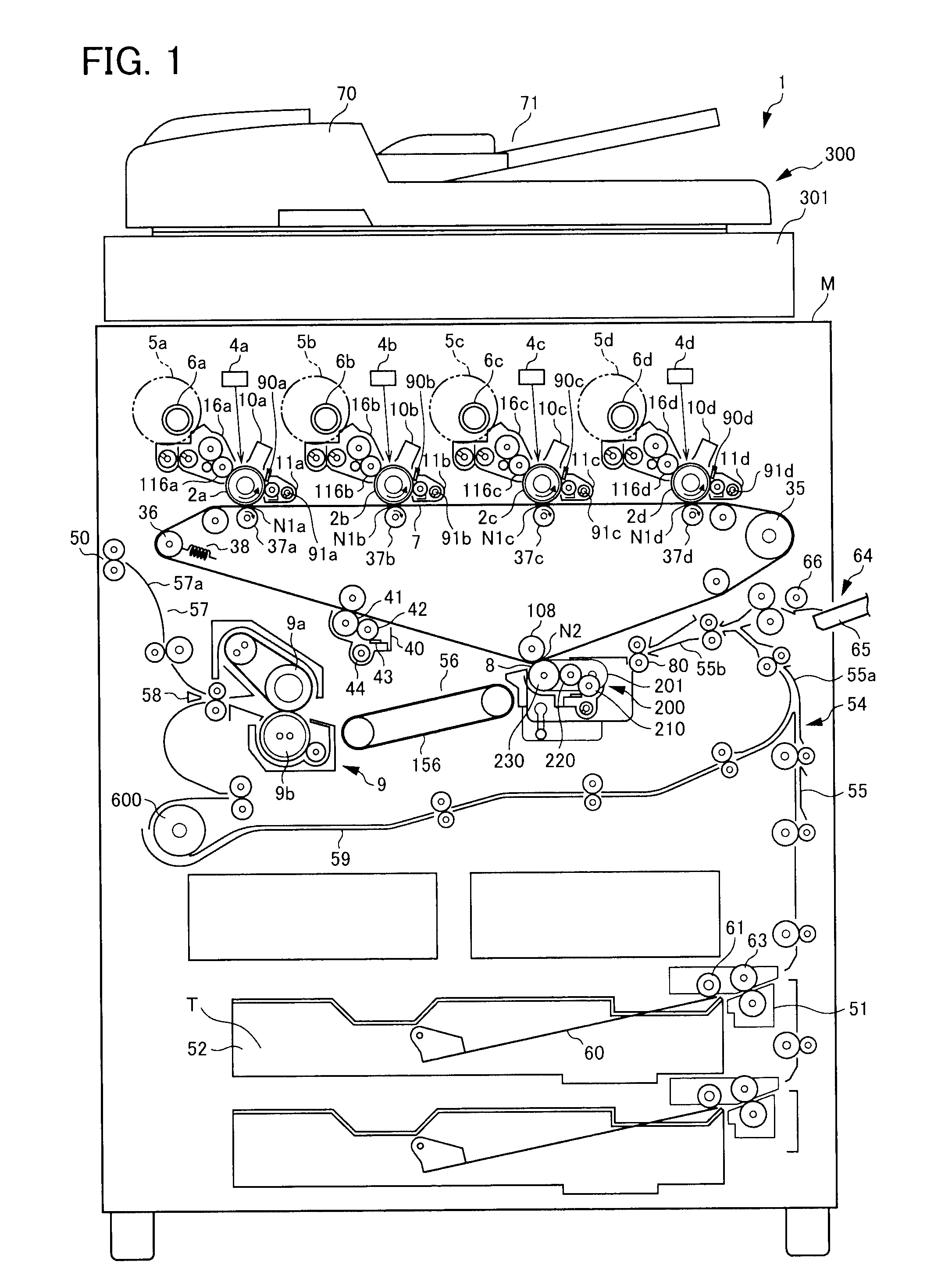
[0024]An overall structure of a color copy machine 1 as an image forming apparatus according to the first embodiment is described referring to FIG. 1. FIG. 1 is a left lateral view showing an arrangement of components of the color copy machine 1. In the present embodiment, a side on which a manual feeding tray 65 (described later) is disposed (a right side in FIG. 1) is a front side of the color copy machine 1.
[0025]The color copy machine 1 as the image forming apparatus includes: an image reading device 300 disposed on an upper side thereof, and a device main body M disposed on a lower side thereof that forms a toner image on a paper T on the basis of image information from the image reading device 300.
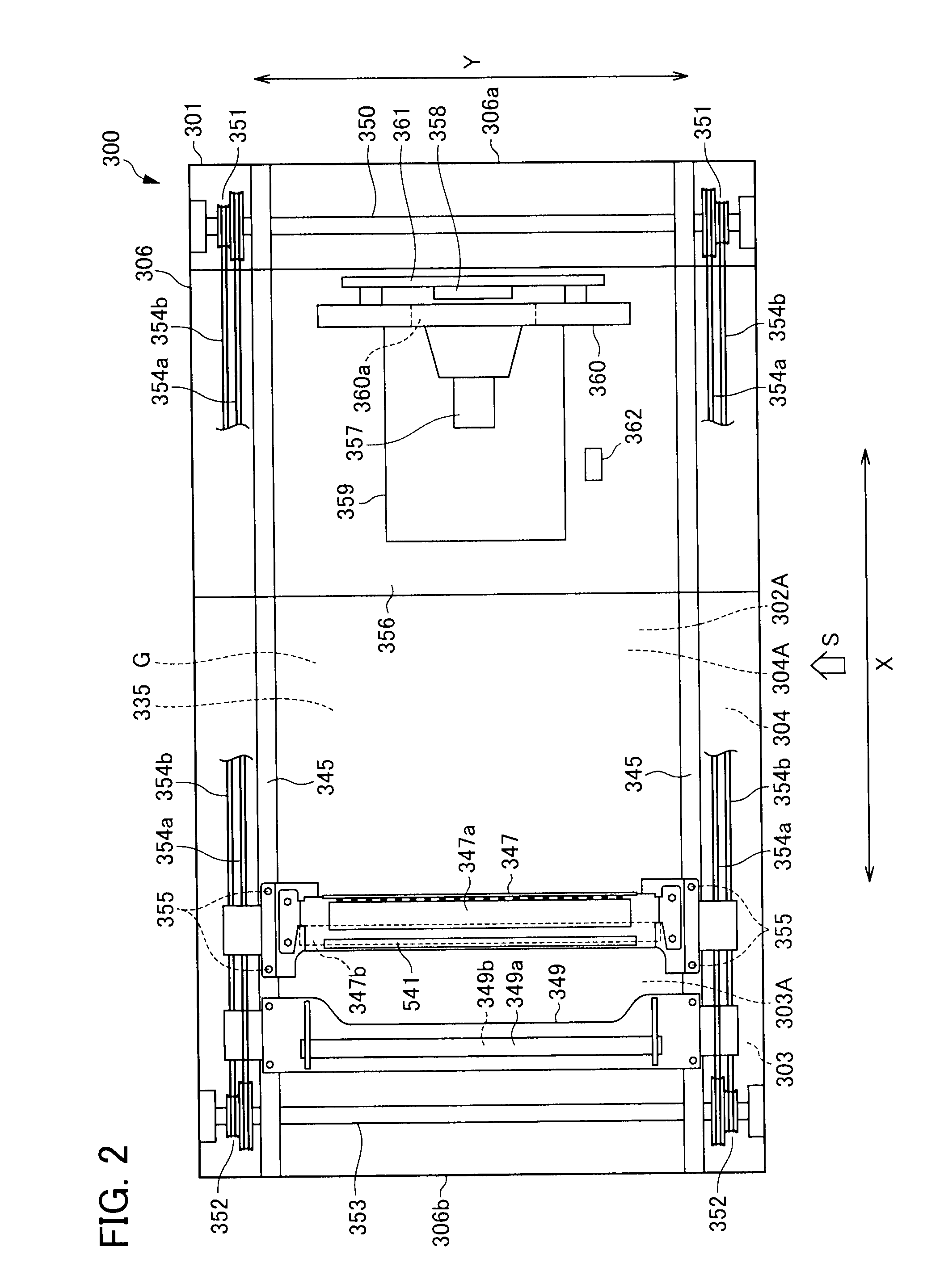
[0026]The image reading device 300 includes an original feeder portion 70 for feeding a predetermined original G (see FIG. 2), and a reader portion 301 for reading an image of the ori...
Example
[0107]Next, a color copy machine according to a second embodiment of the present invention is described with reference to FIGS. 7 to 9. FIG. 7 is a diagram illustrating a light guiding body 505A. FIG. 8 is a perspective view illustrating an LED unit 503A. FIG. 9 is a block diagram including a luminescence control part 450 that controls luminescence of the LED unit 503A. Here, the color copy machine according to the second embodiment has a similar configuration to that of the color copy machine 1 according to the first embodiment, except for the light guiding body 505A. Hereinafter, only the light guiding body 505A, which differs from the color copy machine 1, is described, and descriptions of other components are omitted.
[0108]As shown in FIG. 7, the light guiding body 505A is disposed so that a first end 505a faces the LED unit 503A to which the plurality of LEDs 501 a and 501b is attached and a second end 505b faces the contact glass 335 (see FIG. 3).
[0109]Here, as shown in FIG. 8...
Example
[0127]The first and the second embodiments have been described above as preferred embodiments of the present invention; however, the present invention is not limited thereto and can be carried out in various modes. For example, the copy machine 1 is exemplified in the present embodiment as an image forming apparatus; however, the present invention is not limited thereto and can be a black and white copy machine, a printer, a facsimile machine and a multi-functional printer having functions thereof.
[0128]In addition, the image reading device 300 is formed to be integrated with the device main body M in the first and the second embodiments; however, the present invention is not limited thereto, and the image reading device can be configured with a housing other than the device main body M. For example, the image reading device 300 can be configured to be removable with respect to the device main body M.
[0129]Furthermore, although the image reading device 300 constitutes a portion of t...
PUM
Abstract
Description
Claims
Application Information
- R&D Engineer
- R&D Manager
- IP Professional
- Industry Leading Data Capabilities
- Powerful AI technology
- Patent DNA Extraction
Browse by: Latest US Patents, China's latest patents, Technical Efficacy Thesaurus, Application Domain, Technology Topic.
© 2024 PatSnap. All rights reserved.Legal|Privacy policy|Modern Slavery Act Transparency Statement|Sitemap