
Protective panel with touch input function for electronic apparatus display window

Inactive Publication Date: 2010-01-21
NISSHA PRINTING COMPANY
View PDF2 Cites 48 Cited by
  • Summary
  • Abstract
  • Description
  • Claims
  • Application Information

AI Technical Summary

Benefits of technology

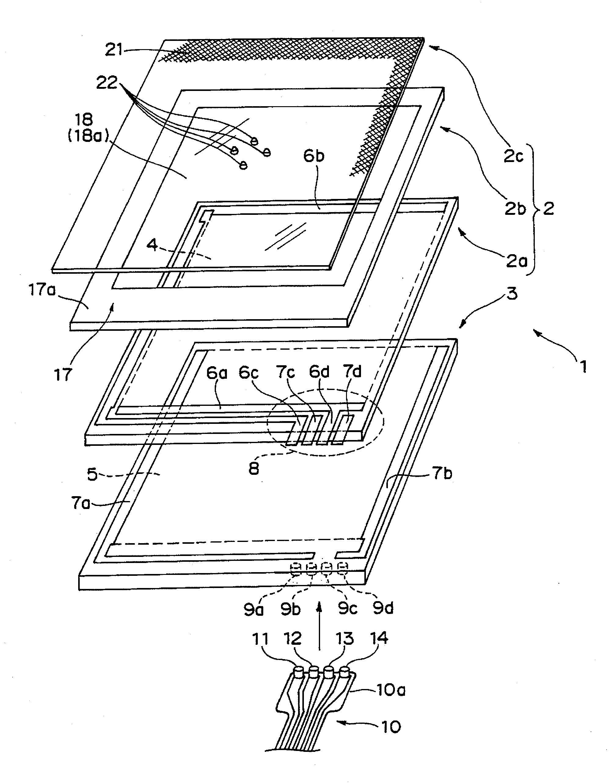
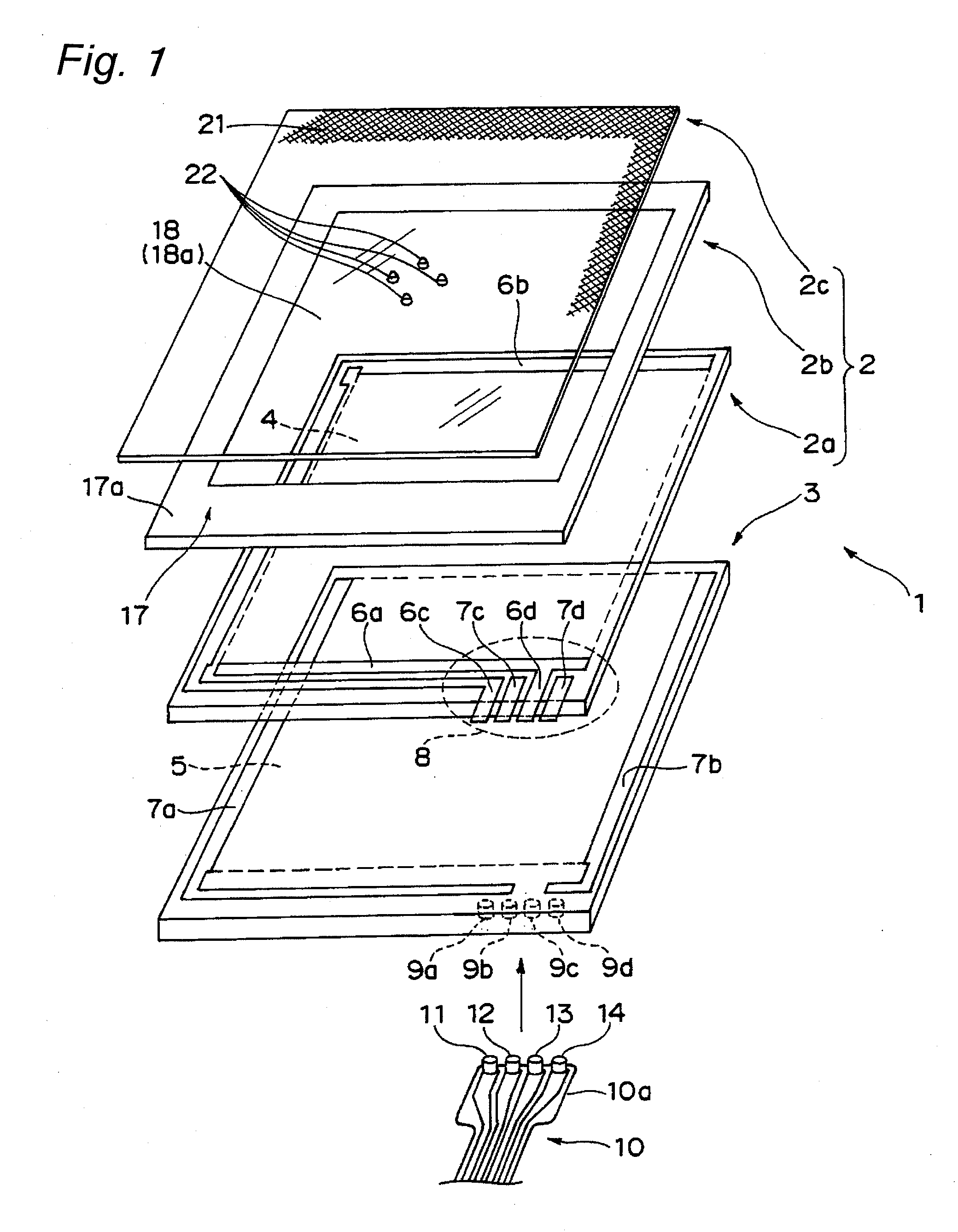
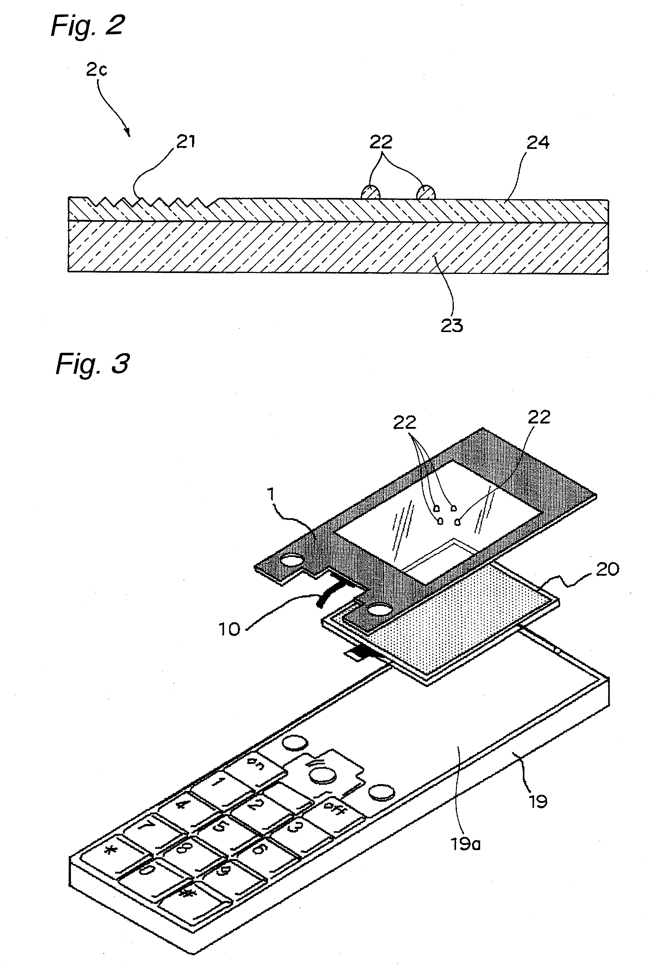
[0028]In accordance with the present invention, since the fine concave / convex portion is partly formed on the surface of the hard coat layer corresponding to the outermost face, it is possible to provide an outside surface with a high additional value that has not been achieved by a conventional protective panel with a touch input function. For example, by partly carrying out a matting process on the surface of the hard coat layer, it is possible to provide high-quality feeling / touch from a design point of view, or by arranging the fine concave / convex portion to be used, e.g., as a home position, for reliable input on a determination key, for prevention of erroneous input, as a scroll bar, for slide opening operation for a portable apparatus, as a camera lens, or for prevention of scratches on a camera lens, on the surface of the hard coat layer, it becomes possible to achieve various functions.

Problems solved by technology

The protective panel 101 with a touch input function for an electronic apparatus display window is adapted to be fitted into a panel fitting section of a casing 119 without a gap to be held so that its touch input face (outside surface) forms the same plane (see FIG. 22), forming an important element of the product surface as the surface of the casing 119; however, in Patent Documents 1 and 2, this face is simply subjected to a hard coating treatment or a low-reflection treatment over the entire face thereof, and the outside surface is poor in an additional value.

Method used


Image

  • Protective panel with touch input function for electronic apparatus display window
  • Protective panel with touch input function for electronic apparatus display window
  • Protective panel with touch input function for electronic apparatus display window

Examples


working example 1

[0126]An ITO film having a thickness of 20 nm was formed on the entire surface of one face of a PET film having a thickness of 0.1 mm by sputtering, and the peripheral edge portion of the ITO film was removed to form a transparent electrode having a rectangular shape with a wide width. Moreover, bus bars to be disposed on the opposing two sides of the transparent electrode laterally, and routing lines for external output from the bus bars were formed by screen-printing silver paste. Moreover, an acrylic plate having the same size as the PET film in its longitudinal and lateral lengths, with a thickness of 0.7 mm, was bonded to the surface of the PET film on the face opposing to the face on which the transparent electrode was formed, by using a baseless transparent adhesive having a thickness of 0.025 mm, and four through holes having a diameter of 1 mm to which pin shafts of an FPC with pins, which will be described later, are inserted, were formed on the edge portion by using a dri...

working example 2

[0135]In working example 1, after the hard coat film in a semi-cured state was partly formed into a mat state, a UV ink of a polyester acrylate-type was applied thereon by using a dispenser to form a fine concave / convex portion, for example, a convex portion (bump) 22A for use as home positions. This convex portion (bump) 22A was cured together with the hard coat film by UV irradiation used when completely curing the hard coat film. The other processes are the same as those of working example 1.

[0136]In addition to the effects of working example 1, this protective panel enables blind touch operation.

[0137]By properly combining the arbitrary embodiments of the aforementioned various embodiments, the effects possessed by the embodiments can be produced.


PUM


Abstract

A protective panel with a touch input function for an electronic apparatus display window is adapted to be fitted into a panel fitting section of a casing having an opening without a gap so as to be held therein such that the outside surface thereof forms the same plane, with a display disposed the panel below being protected in such a manner as to be visually recognized from the outside through a transparent window portion, wherein a fine concave / convex portion is partly formed on the surface of a hard coat layer.

Description

TECHNICAL FIELD[0001]The present invention relates to a protective panel with a touch input function for a display window of an electronic apparatus that is used for various applications such as portable information terminals, such as PDAs and handy terminals, office automation equipment, such as copying machines and facsimiles, as well as smart phones, cell phones, cameras, portable game apparatuses, electronic dictionaries, car navigation systems, small-size personal computers, and various home electronics, and that has an outside surface having a high additional value that has not been achieved by a conventional protective panel with a touch input function.BACKGROUND ART[0002]A casing for use in an electronic apparatus, such as a cell phone and a smart phone, is generally constructed by combining a front face casing and a back face casing made of a synthetic resin. More specifically, as shown in FIG. 21, a protective panel 100 is secured onto the surface of the front face casing ...

Claims


Application Information

Patent Timeline
IPC IPC(8): G06F3/041G06F3/0488
CPCG06F1/1624G06F1/1686G06F3/045G06F3/04886G06F2203/04809G06F3/0412
Inventor NISHIKAWA, KAZUHIROHASHIMOTO, TAKAOKAI, YOSHIHIROSUNAHASE, TAKAKUNINAKAMURA, KAZUTO
Owner NISSHA PRINTING COMPANY
Learn More