Multi-color image processing apparatus and signal processing apparatus

a signal processing and image processing technology, applied in the field of image processing techniques, can solve the problems of difficult to capture a moving picture, difficult to further increase the image data read rate of imagers, etc., and achieve the effect of high image quality and increased resolution of moving picture with first-color components

Active Publication Date: 2010-01-21
PANASONIC CORP
View PDF5 Cites 21 Cited by
  • Summary
  • Abstract
  • Description
  • Claims
  • Application Information

AI Technical Summary

Benefits of technology

[0032]According to the present invention, even if a moving picture with first-color components (that are normally G components) has a lot of aliasing components, motion compensation is done using a moving picture with no aliasing components. As a result, the resolution of the moving picture with the first-color components can be increased and a multi-color moving picture of high image quality can be obtained eventually.

Problems solved by technology

However, it is difficult to further increase the image data read rate for imagers (such as CCDs and CMOS image sensors) that are used extensively now in those image capture devices.
That is why it is not easy to capture a moving picture with both the resolution and frame rate kept high.

Method used


Image

  • Multi-color image processing apparatus and signal processing apparatus
  • Multi-color image processing apparatus and signal processing apparatus
  • Multi-color image processing apparatus and signal processing apparatus

Examples


embodiment 1

[0089]Hereinafter, a first specific preferred embodiment of a multi-color image processor according to the present invention will be described with reference to FIG. 5.

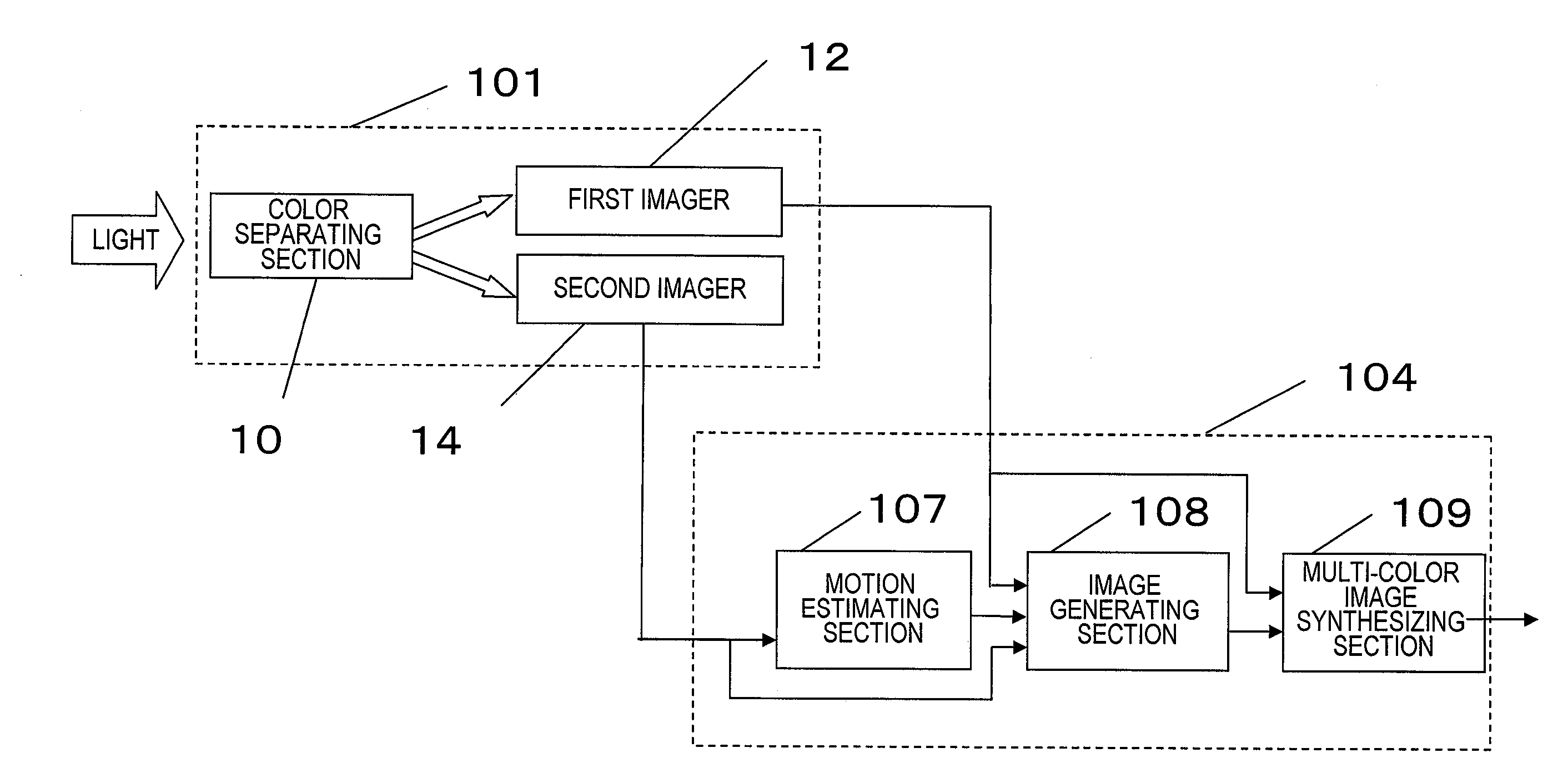
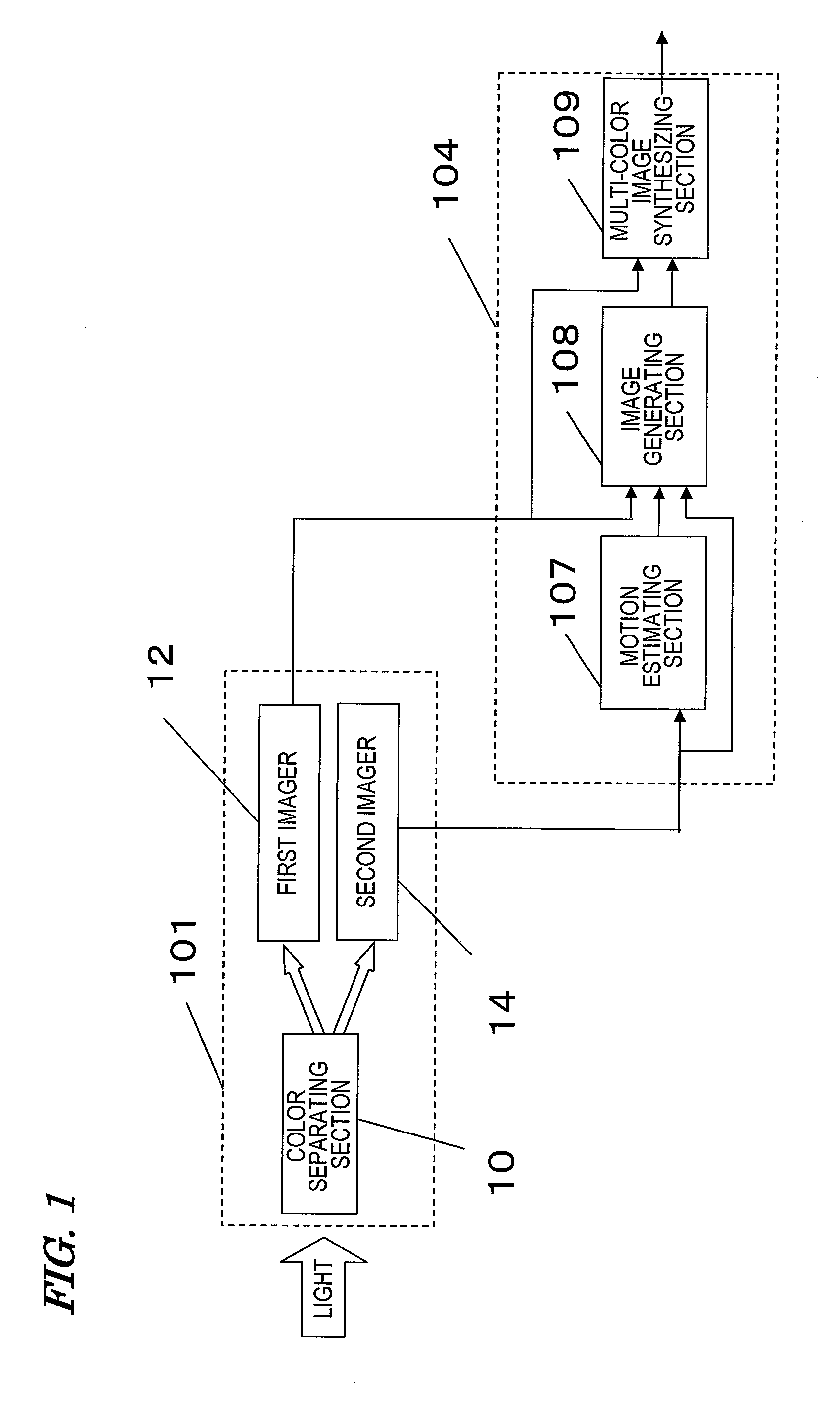
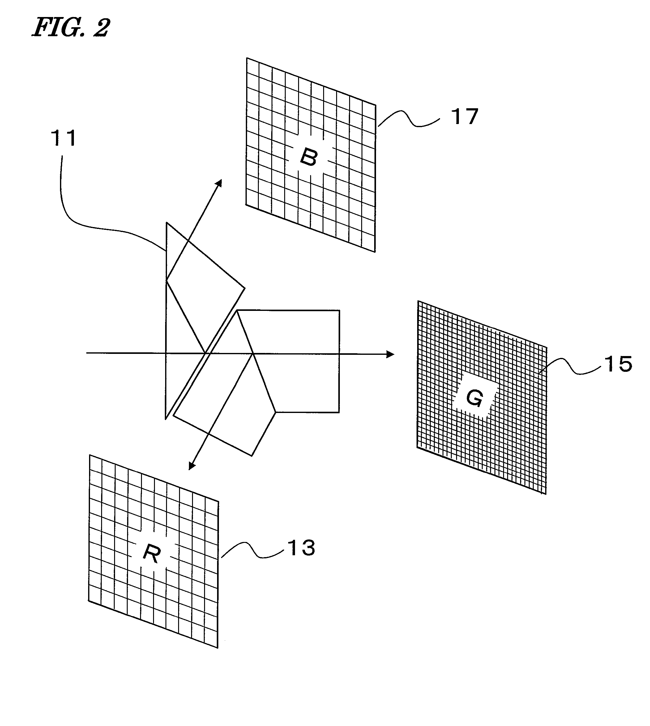
[0090]The multi-color image processor of this preferred embodiment includes an image capturing section 101 for separating incoming visible radiation into R, G and B rays to obtain the moving pictures (i.e., the original images 401 shown in FIG. 4) described above, a storage section 106 for storing the original images, and a signal processing section 104 for performing processing of increasing the temporal and spatial resolutions using the original images that are stored in the storage section 106.

[0091]The storage section 106 includes a memory 103 that stores the original images and a writing control section 102 that writes the original images on the memory 103. As the memory 103, any suitable storage device that can store image data may be used. However, the memory 103 does not have to be built in this processor but ...

embodiment 2

[0194]Hereinafter, a second preferred embodiment of a multi-color image processor according to the present invention will be described.

[0195]In the device of the first preferred embodiment described above, the arrangement of pixels in the image capturing section 101 is accessed on a line-by-line basis, and such access can be made by both CCD imagers and CMOS imagers. On the other hand, in this preferred embodiment, the arrangement of pixels is accessed on a pixel-by-pixel basis, not on a line-by-line basis. Such an image capturing method can be carried out easily using randomly-accessible imagers such as CMOS imagers.

[0196]The configuration of the processor of this preferred embodiment is basically the same as the one illustrated in FIG. 5. But the imagers of the image capturing section 101 of this preferred embodiment operate differently from their counterparts of the first preferred embodiment. Thus, the following description of the second preferred embodiment will be focused on o...

embodiment 3

[0203]In the first and second preferred embodiments described above, the exposure process time during the image capturing operation is roughly at most as long as one field period. However, this is just an example and the exposure process time of the G component image could be extended to n times as long as one field period (where n is the number of fields to read all pixels).

[0204]If the exposure process time of the G component image is defined to be longer than one field period, then the sampling process represented by Equations (3) to (5) should be changed partially. However, the light that would otherwise be wasted during the field periods other than the one for actually reading pixels can be used effectively according to this method.

[0205]Hereinafter, it will be described using a simple example how to formulate the sampling process H. If a picture made up of two frames (i.e., t=1, 2), each consisting of two horizontal pixels (i.e., x=1, 2) by two vertical pixels (i.e., y=1, 2), ...


PUM


Abstract

A multi-color image processor according to the present invention includes an image capturing section 101 and a signal processing section 104. The image capturing section 101 includes a color separating section 10 for separating visible radiation into at least two light rays with first- and second-color components, respectively, and first and second imagers 12 and 14 that receive the light rays with the first- and second-color components. The image capturing section 101 gets images with the first- and second-color components by making the first imager 12 decimate pixels to read, but making the second imager 14 read every pixel, on a field-by-field basis on respective arrangements of pixels of the first and second imagers 12 and 14. The signal processing section 104 includes: a motion estimating section 107 for estimating, based on the images with the second-color components, a motion in a moving picture made up of images with the second-color components and outputting motion information; an image generating section 108 for generating a synthetic image of the first-color components of respective fields based on the images with the first-color components and the motion information and outputting it as a first synthetic image with a higher spatial resolution than the images with the first-color components; and a multi-color image synthesizing section 109 for generating and outputting a multi-color moving picture with the first- and second-color components based on the first synthetic image and the images with the second-color components.

Description

TECHNICAL FIELD[0001]The present invention relates to an image processing technique for generating a color moving picture with the resolution and frame rate both increased.BACKGROUND ART[0002]In the field of technology of image capture devices, the image qualities achieved by digital camcorders and digital still cameras have been significantly improved, and the number of functions provided for a single image capture device has been rapidly increased, these days. A list of main indices indicating the image quality of a moving picture generated by any of these image capture devices includes the number of pixels per frame (i.e., the resolution), the number of frames per second (i.e., the frame rate), and the ratio of an image signal to noise (SNR). There are various levels of resolutions available from the number of pixels that is barely usable for a QCIF compliant TV phone to as high a resolution as more than 10 million pixels for a digital single-lens reflex camera. Likewise, there a...

Claims


Application Information

Patent Timeline
Patent Type & Authority Applications(United States)
IPC IPC(8): H04N5/228
CPCH04N5/23232H04N9/09H04N9/045H04N23/60H04N23/951H04N23/84H04N23/13
Inventor AZUMA, TAKEONOBORI, KUNIOIMAGAWA, TAROKANAMORI, KATSUHIRO
Owner PANASONIC CORP
Why Eureka
Try Eureka