
Optical tomographic image photographing apparatus

Active Publication Date: 2010-01-21
NIDEK CO LTD
View PDF0 Cites 23 Cited by
  • Summary
  • Abstract
  • Description
  • Claims
  • Application Information

AI Technical Summary

Benefits of technology

[0010]An object of the invention is to overcome the problems described above and to provide a fundus photographing apparatus which allows for smooth adjustment of the optical path length with respect to an examined object.

Problems solved by technology

However, the technique described above requires long time to perform the adjustment of the optical path length because the optical-path-length varying optical member should be moved from the position at which the optical path length of the reference light is shortest or from the position at which the optical path length of the reference light is longest.
In addition, a tomographic image desired by an examiner could not be displayed if the examinee's eye blinks when the optical-path-length varying optical member is located at a position at which the previously specified tomographic image (e.g., an inverted image) is obtained during the adjustment of the optical path length.

Method used


Image

  • Optical tomographic image photographing apparatus
  • Optical tomographic image photographing apparatus
  • Optical tomographic image photographing apparatus

Examples


Embodiment Construction

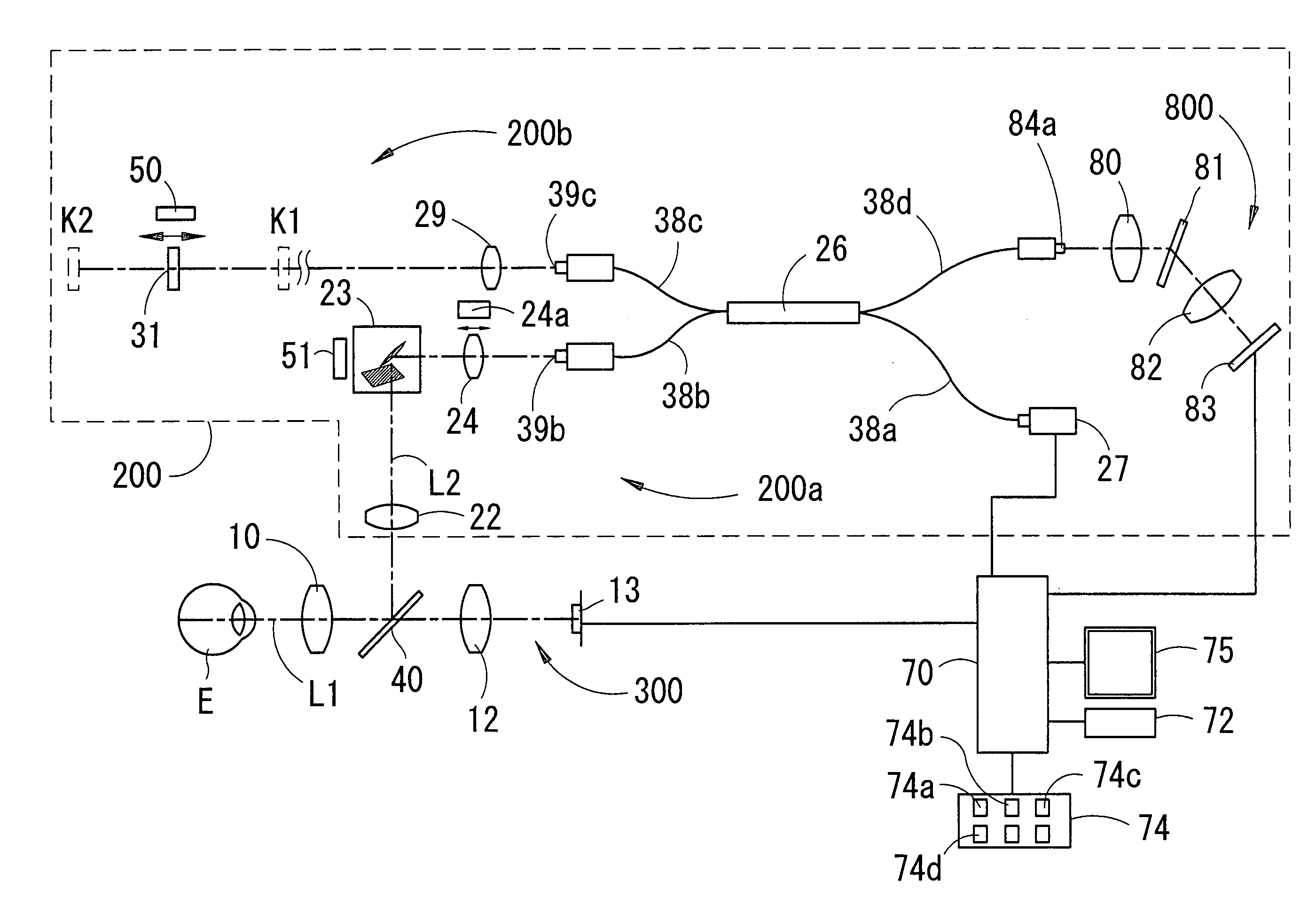
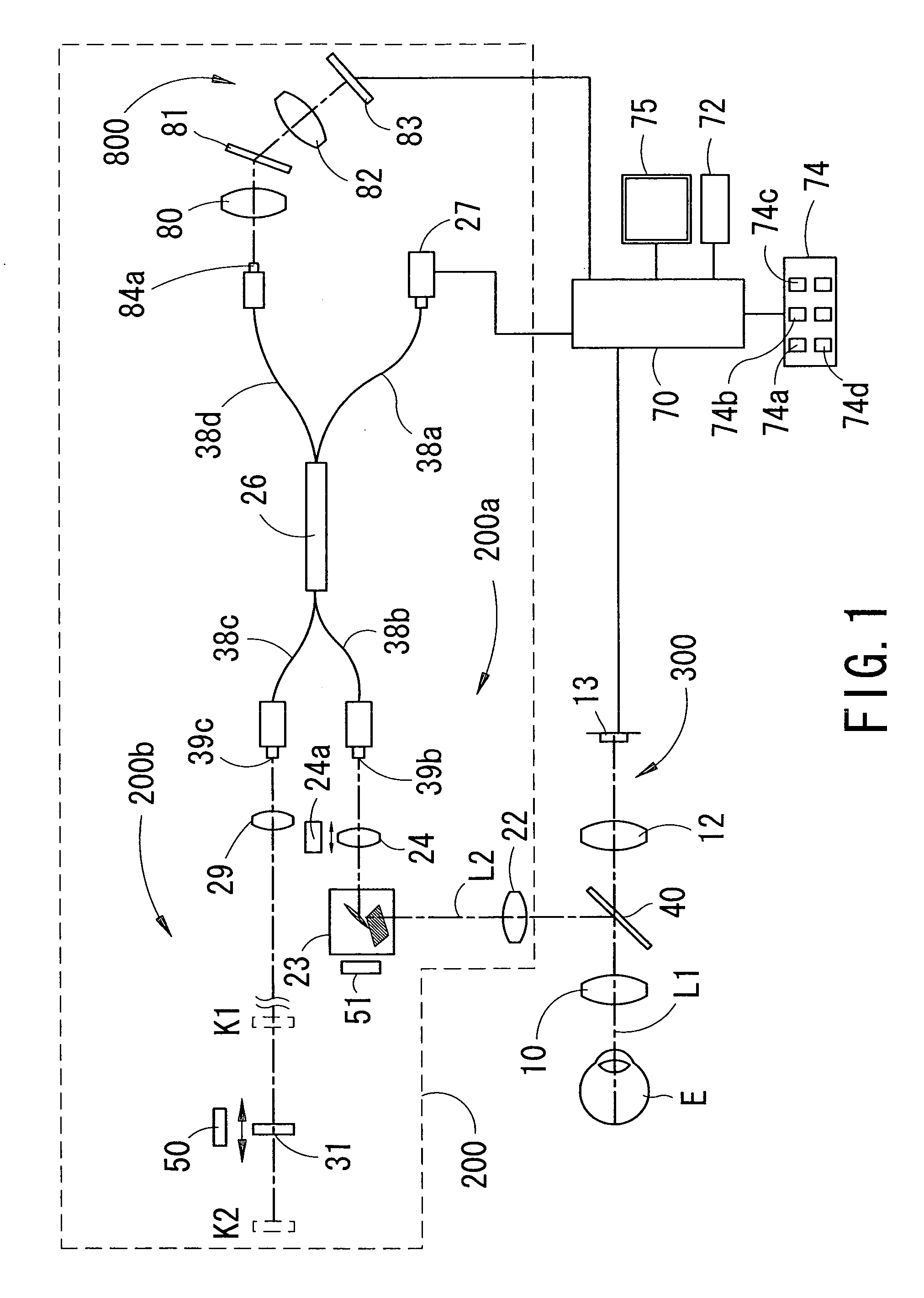
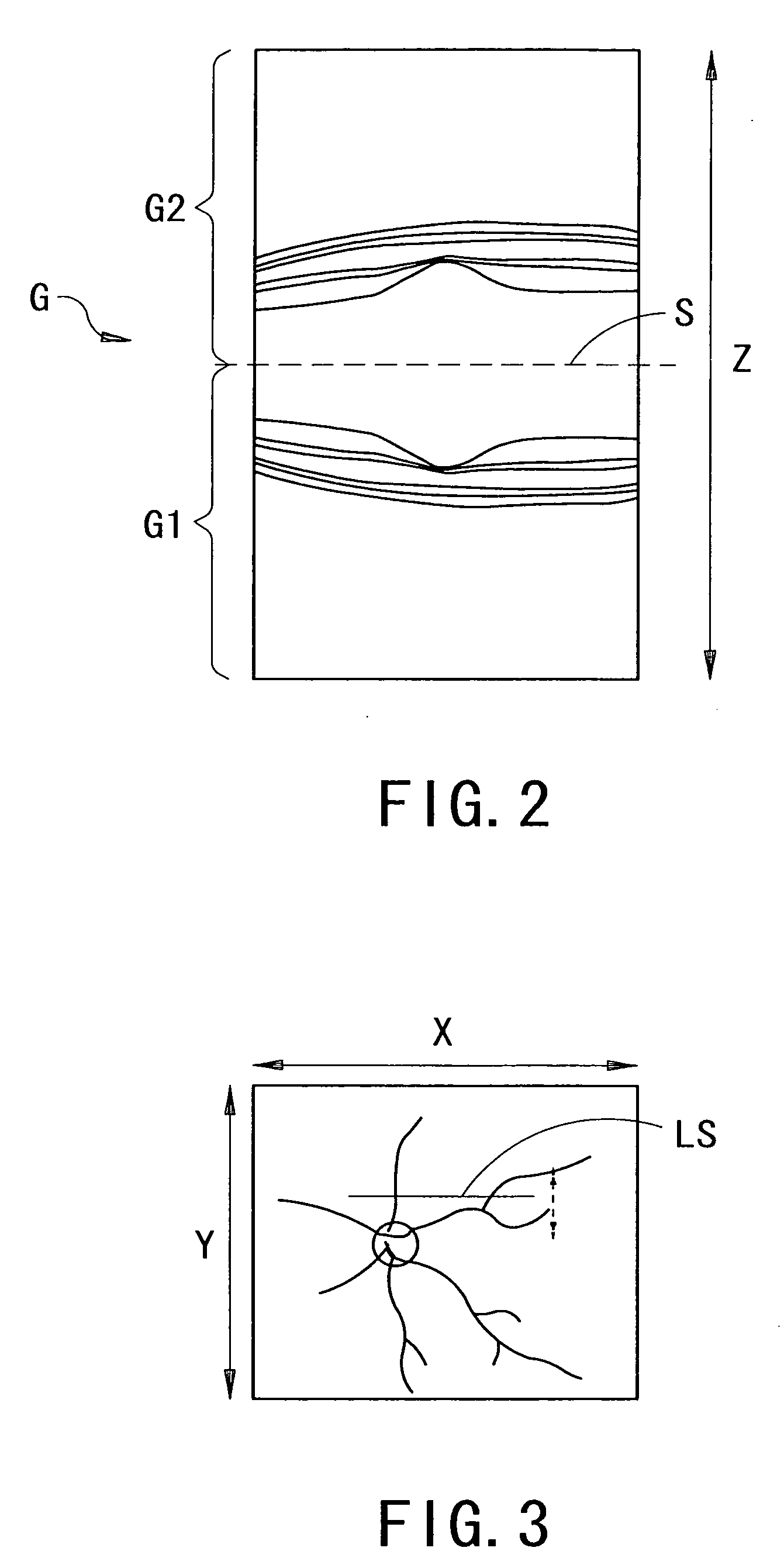
[0022]A detailed description of one preferred embodiment of an optical tomographic image photographing apparatus embodied by the present invention is provided below with reference to the accompanying drawings. FIG. 1 is a view showing an optical system and a control system of the optical tomographic image photographing apparatus according to the present preferred embodiment of the present invention. In the descriptions provided below, a fundus photographing apparatus, which is one of ophthalmic photographing apparatuses, is taken as an example. Hereinafter, a depth direction of an examinee's eye E is referred to as a Z-direction (a direction of an optical axis L1), a horizontal direction on a plane which is perpendicular to the depth direction is referred to as an X-direction, and a vertical direction is referred to as a Y-direction.

[0023]In FIG. 1, the optical system is provided with an interference optical system (an OCT optical system) 200 and a fundus observation optical system ...


PUM


Abstract

An apparatus has an optical system detecting spectral information and having an optical scanner and a driving unit changing the optical path length by moving an optical member, a monitor, a control unit obtaining a tomographic image by performing Fourier analysis on the information and displaying the obtained image, and a unit previously setting an image on the monitor, in which the member is moved from an initial position and presence or absence of the tomographic image is determined, when the presence is detected, whether the tomographic image is normal or inverted is determined, and when the tomographic image is not the set image, the member is moved to obtain the set image, and when the tomographic image is the set image, the member is moved so that a position of the tomographic image in the depth direction coincides with a predetermined adjustment position and the driving unit is stopped.

Description

BACKGROUND OF THE INVENTION[0001]1. Field of the Invention[0002]The present invention relates to an optical tomographic image photographing apparatus arranged to photograph a tomographic image of an examined object.[0003]2. Description of Related Art[0004]Conventionally, as an optical tomographic image photographing apparatus arranged to photograph a tomographic image of an examined object, there is known an optical coherence tomograph (OCT) using low coherent light (see Japanese Patent Application Unexamined Publication No. 2006-212153). This apparatus is used for obtaining a tomographic image of a living body part such as an eyeball and a skin, for example.[0005]In order for such an apparatus to obtain a tomographic image which is formed by interference light of measurement light projected onto the examined object and reference light, it is necessary to perform adjustment of the optical path length by moving an optical-path-length varying optical member (e.g., a reference mirror)....

Claims


Application Information

Patent Timeline
IPC IPC(8): G01B9/02A61B3/14
CPCA61B3/102G01N21/4795G01B9/02064G01B9/0203G01B9/02089G01B9/02091G01B9/02078G01B9/02083G01B9/02044
Inventor YAMADA, YOSHIYUKIHIGUCHI, YUKIHIROSATAKE, NORIMASATORII, HISANARI
Owner NIDEK CO LTD
Features
  • Generate Ideas
  • Intellectual Property
  • Life Sciences
  • Materials
  • Tech Scout
  • Unparalleled Data Quality
  • Higher Quality Content
  • 60% Fewer Hallucinations
Learn More