Illuminating device with heat dissipating element

a technology of heat dissipation element and illumination device, which is applied in the direction of semiconductor devices for light sources, lighting and heating equipment, lighting support devices, etc., can solve the problems of reducing operation life, slow heat dissipation, and relative small thermal conductivity coefficien

Inactive Publication Date: 2010-01-21
FOXSEMICON INTEGRATED TECH INC
View PDF0 Cites 27 Cited by
  • Summary
  • Abstract
  • Description
  • Claims
  • Application Information

AI Technical Summary

Benefits of technology

[0005]Generally, heat produced by the illuminating device can be transferred via air convection and dissipated into the external environment. However, the air has a relatively small thermal conductivity coefficient, and, as such, heat dissipation is slow. Eventually, the heat accumulated around the illuminating device will influence the light intensity of the LED, thereby reducing the operation life thereof.

Problems solved by technology

However, the air has a relatively small thermal conductivity coefficient, and, as such, heat dissipation is slow.
Eventually, the heat accumulated around the illuminating device will influence the light intensity of the LED, thereby reducing the operation life thereof.

Method used


Image

  • Illuminating device with heat dissipating element
  • Illuminating device with heat dissipating element
  • Illuminating device with heat dissipating element

Examples


first embodiment

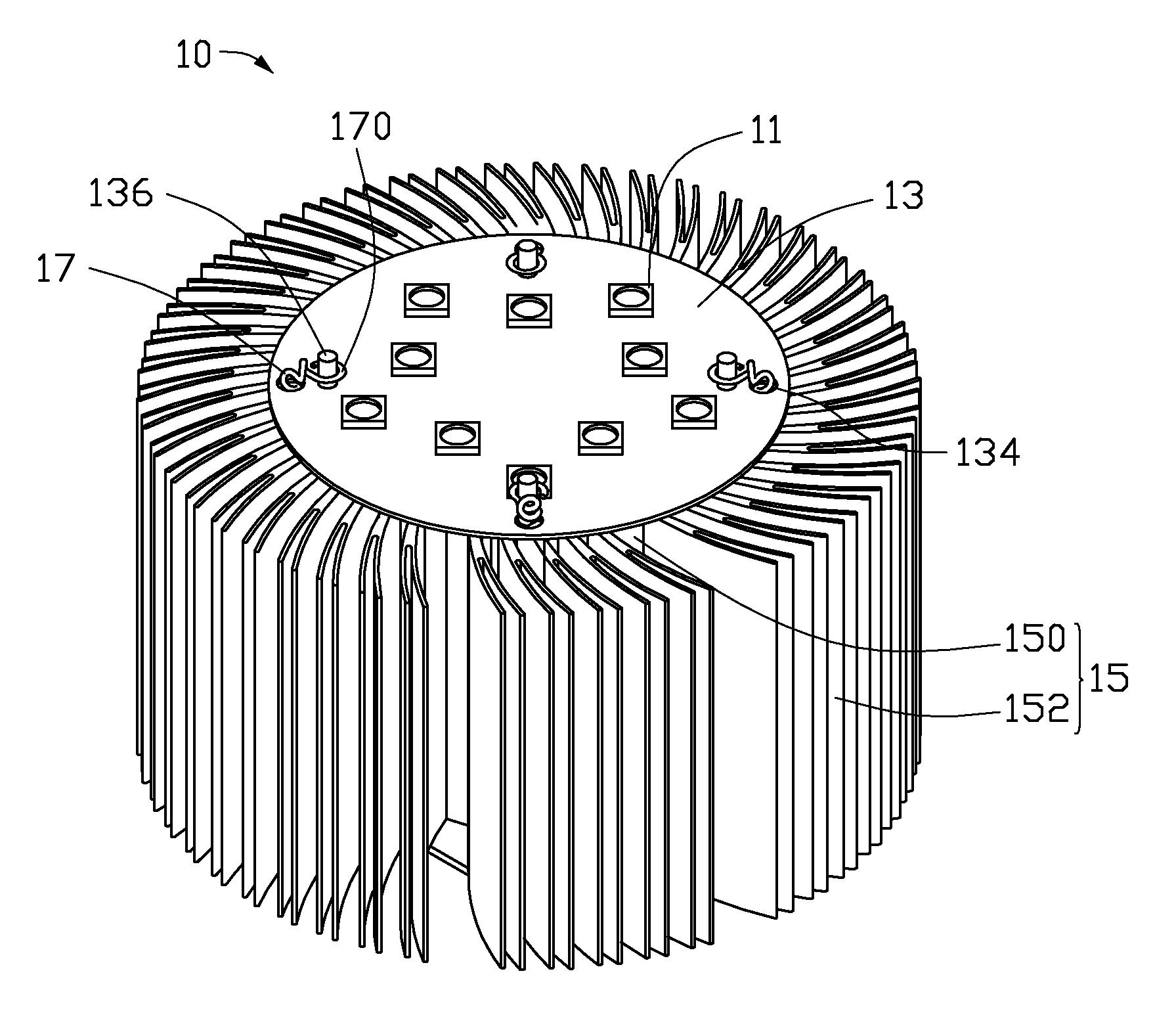
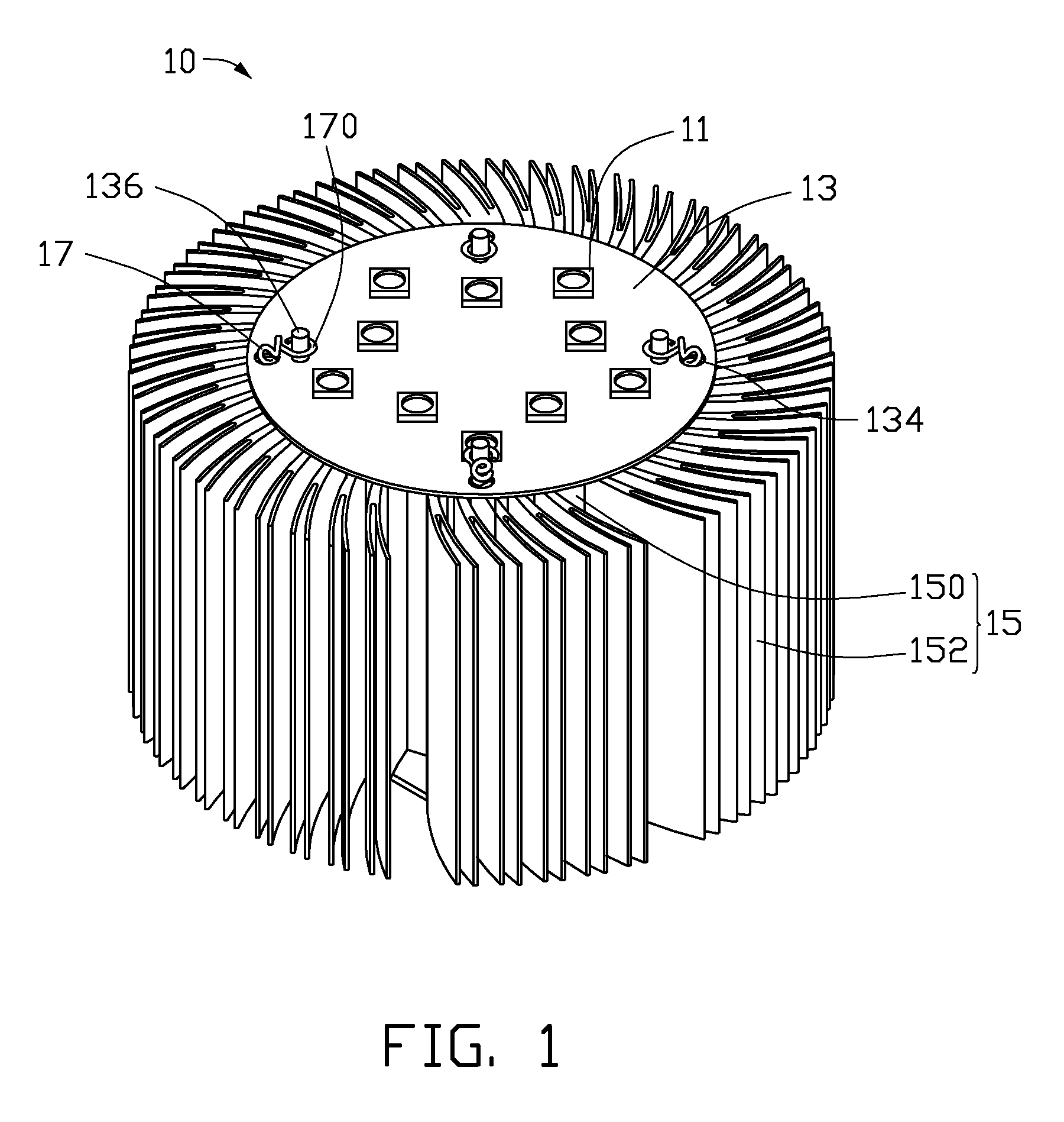
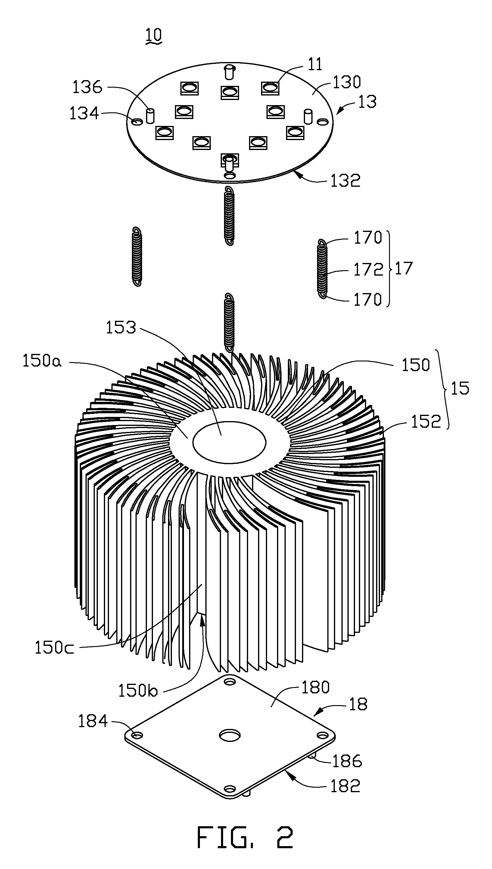
[0012]Referring to FIGS. 1 and 2, an illuminating device 10 in accordance with a first embodiment includes at least one light source, a circuit board 13, a heat dissipating device 15, a plurality of resilient elements, and a supporting board 18 having a first surface 180 and a second surface 182 facing away from the first surface 180.

[0013]In the first embodiment, the at least one light source consists a plurality of LEDs 11. The plurality of LEDs 11 can be selected from the group consisting of white LED, green LED, red LED, and blue LED.

[0014]The circuit board 13 includes a first surface 130 and a second surface 132 facing away from the first surface 130. The plurality of light sources 11 is electrically attached to the first surface 130 of the circuit board 13. In the first embodiment, the circuit board 13 is a metal core printed circuit board (MCPCB). In alternative embodiments, the circuit board 13 can be a ceramic circuit board, a glass fiber board, etc.

[0015]In the first embod...

second embodiment

[0022]Referring to FIG. 3, an illuminating device 30 in accordance with a second embodiment includes at least one light source 31, a circuit board 33, a heat dissipating device 35, a plurality of resilient elements 37. The heat dissipating device 35 includes a flat substrate 350 and fins 352 formed on the substrate 350. A thermal interface material 36 is applied between the circuit board 33 and the substrate 350 in order to fill air spaces therebetween thereby promoting efficient heat transfer. The resilient elements 37 are configured for connecting the circuit board 33 with the substrate 350 and preloading pulling force therebetween, thereby promoting efficient heat transfer from the circuit board to the heat dissipating device 35.


PUM


Abstract

An exemplary illuminating device includes a circuit board, a plurality of light sources, a thermal interface material, and a plurality of stretched resilient elements. The circuit board has a first surface and a second surface at an opposite side of the circuit board to the first surface. The plurality of light sources is electrically mounted on the first surface of the circuit board. The heat dissipating device is attached on the second surface of the circuit board. The thermal interface material is applied between the second surface of the circuit board and the heat dissipating device. The plurality of resilient elements are configured for connecting the circuit board with the heat dissipating device and providing a pulling force therebetween.

Description

BACKGROUND[0001]1. Technical Field[0002]The present invention relates to illuminating devices, and particularly, to an illuminating device incorporating a heat dissipating element.[0003]2. Discussion of Related Art[0004]At present, light-emitting diodes (LEDs) are popularly used as illuminating devices.[0005]Generally, heat produced by the illuminating device can be transferred via air convection and dissipated into the external environment. However, the air has a relatively small thermal conductivity coefficient, and, as such, heat dissipation is slow. Eventually, the heat accumulated around the illuminating device will influence the light intensity of the LED, thereby reducing the operation life thereof.[0006]Therefore, what is needed is an illuminating device to overcome the above-described deficiencies.BRIEF DESCRIPTION OF THE DRAWINGS[0007]Many aspects of various exemplary embodiments can be better understood with reference to the following drawings. The components in the drawi...

Claims


Application Information

Patent Timeline
Patent Type & Authority Applications(United States)
IPC IPC(8): F21V9/00F21S4/00F21V29/00
CPCF21V17/162F21V19/005F21V29/004F21V29/85F21V29/74F21V29/763F21Y2101/02F21Y2115/10
Inventor CHIANG, KUO-FENGCHENG, YI-KAILU, YING-CHIEHCHEN, PING-YUHSU, HUNG-KUANG
Owner FOXSEMICON INTEGRATED TECH INC
Why Eureka
Try Eureka