Packet ring network system, packet forwarding method and node

a packet ring network and packet ring technology, applied in the field of packet ring network system, can solve problems such as failure recovery operation, and achieve the effect of improving resource (the two nodes)

Inactive Publication Date: 2010-01-21
NEC CORP
View PDF17 Cites 20 Cited by
  • Summary
  • Abstract
  • Description
  • Claims
  • Application Information

AI Technical Summary

Benefits of technology

[0057]According to the present invention, the client device distributes the packets to the two nodes included in the virtual redundant node. Thus, each of the two nodes included in the virtual redundant node contributes to the forwarding of the packet from the client device. There is no such a state wherein one of the two nodes simply has to wait, thus improving resource (the two nodes included in the virtual redundant node) utilization efficiency.
[0058]The storage unit included in each node of the virtual redundant node can learn and store the corresponding relationship between the address of each client device and the address of the node connected to the client device, based on the packet generated as the same packet as the broadcast data packet or unicast data packet received by the receiver (receiving portion) of the same node, or the unicast data packet taken from the ringlet. Thus, each node included in the virtual redundant node learns and stores the corresponding relationship between the addresses. Even when a failure has occurred in a link between one node and the client device, the other node stores the address corresponding relationship, and does not need to learn the new corresponding relationship. As a result, the failure in the link between the one node and the client device can rapidly be recovered.
[0059]When a failure has occurred in one of the links between the two nodes of the virtual redundant node and the client device, the client device sends a packet to the node connected to the link without the failure. When a failure has occurred in the other one of the links between the nodes of the virtual redundant node and the client device, the filter unit of each node included in the virtual redundant node permits output of packet forwarded from any ringlets to the sender (sending portion) for client device. Even if a failure has occurred in the link between the one node and the client device, the packet is sent from the client device to the node connected to thereto through the link without the failure. When a failure has occurred in the link between the other node of the virtual redundant node and the client device, the filter unit of each node included in the virtual redundant node permits the packet forwarded from any ringlets to be output to the sender for client device. Thus, at the time when no link failure has occurred, the node connected to the link without the failure sends the packet to the client. This is used to be done by the other node. In addition, the node without the link failure is responsible for sending the packets to the client device. As a result, the packets can be sent from the client device to the virtual redundant node and from the virtual redundant node to the client device, without having an effect on the entire packet ring network.

Problems solved by technology

However, the above specification does not define an operation for failure recovery when a failure has occurred in the connection of the client device under each RPR node (i.e. the link between the node and the client device).

Method used


Image

  • Packet ring network system, packet forwarding method and node
  • Packet ring network system, packet forwarding method and node
  • Packet ring network system, packet forwarding method and node

Examples


first embodiment

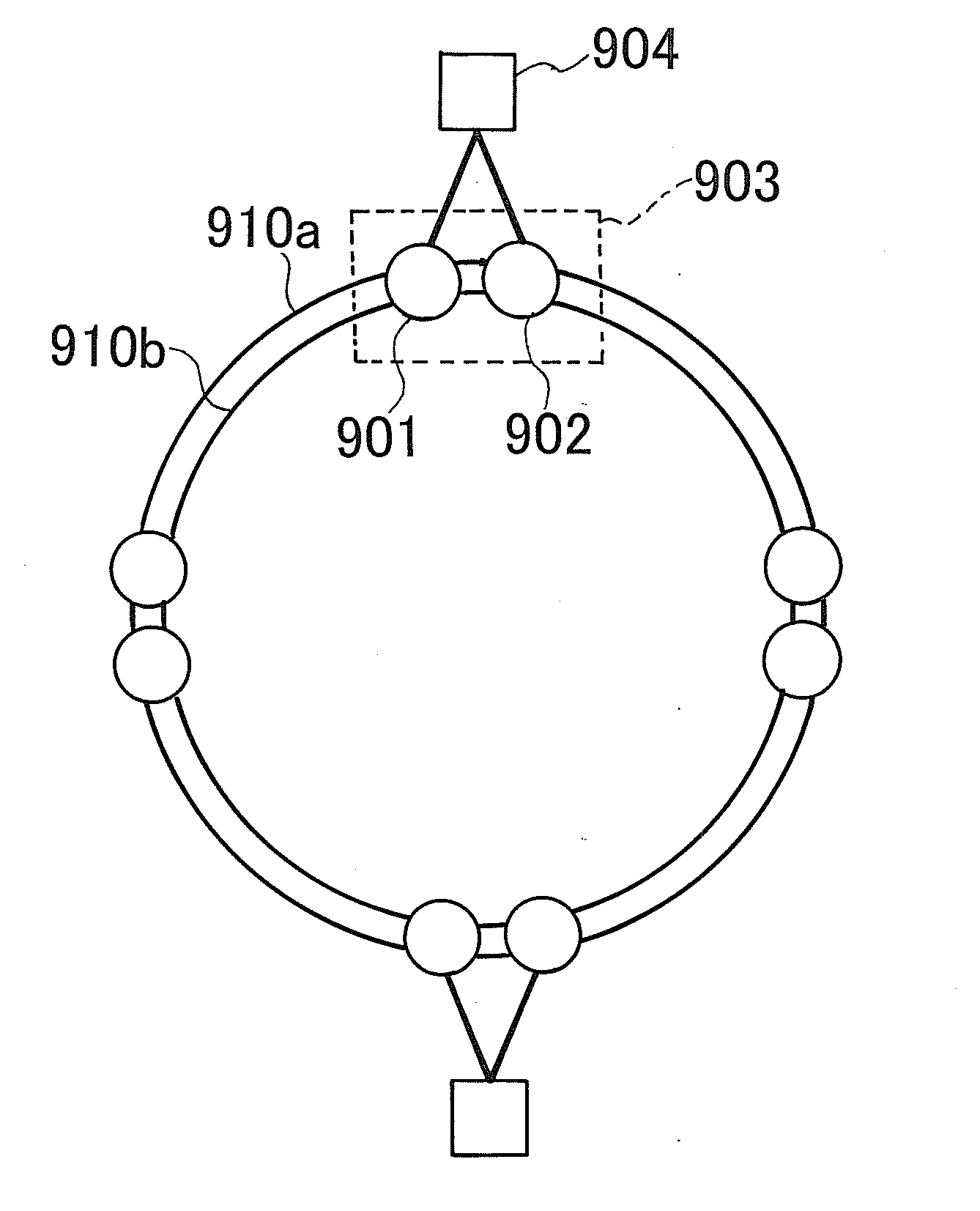
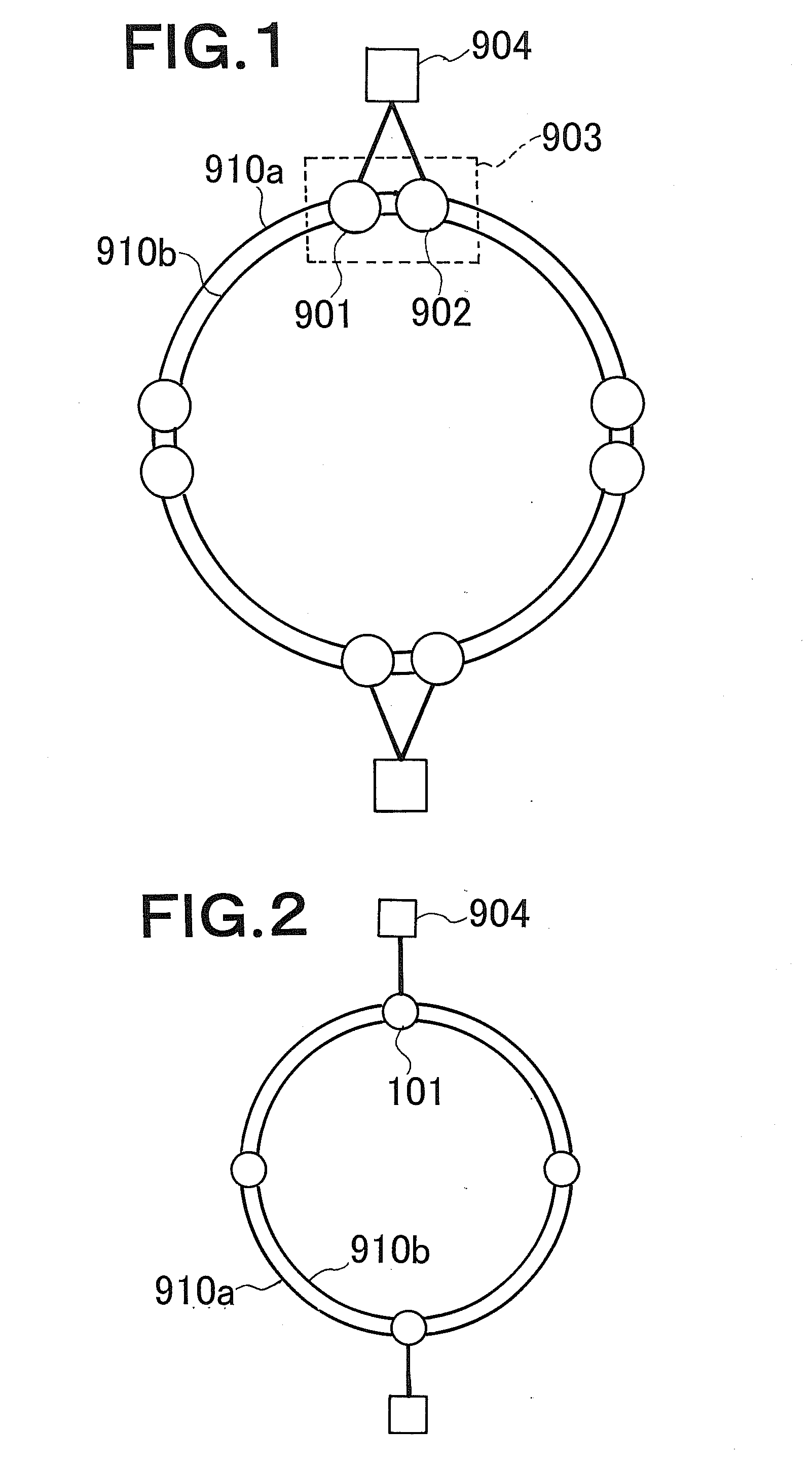
[0094]FIG. 1 is an explanatory diagram showing an example of a packet ring network system of the present invention. The packet ring network system of the present invention includes a ring (a packet ring wherein nodes are connected in a ring configuration). The packet ring network system has a combination of two RPR nodes (hereinafter referred to as nodes) 901 and 902 and redundantly includes the two nodes 901 and 902. A combination 903 of the two nodes acts as virtually as one node. As shown in FIG. 1, the packet ring network system has four combinations of the two nodes. However, the number of combinations of the two nodes is not limited to four. Hereinafter, the combination of the two nodes is noted as a virtual redundant node. The virtual redundant node includes two adjacent nodes. The virtual redundant nodes of the packet ring network system operate the same. If the client device is connected to the virtual redundant node, the device is connected thereto by links of its two node...

second embodiment

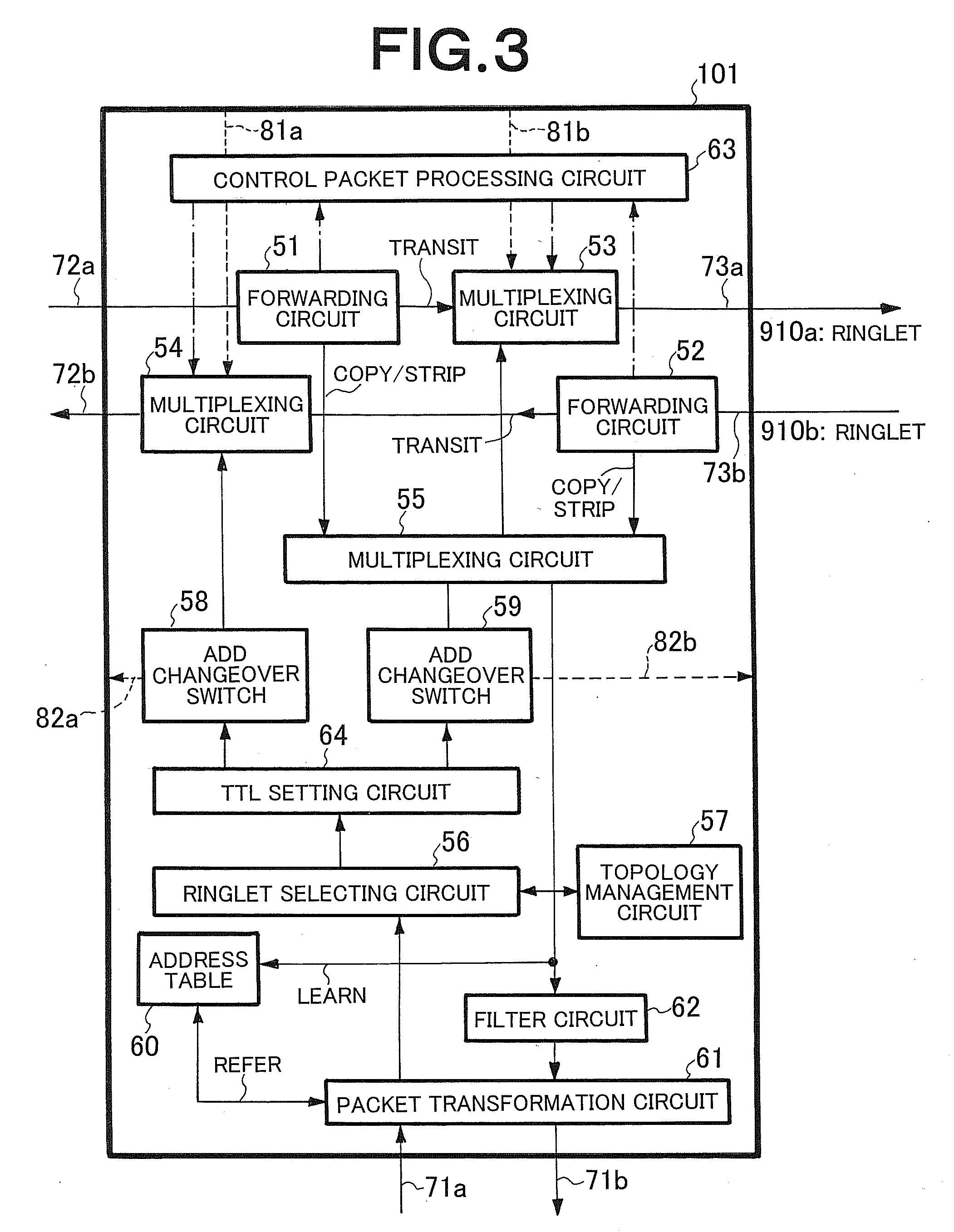
[0209]FIG. 12 is an explanatory diagram exemplarily showing a configuration of a node according to a second embodiment of the present invention. The same constituent elements are identified by the same reference numerals of FIG. 3, thus will not specifically be described again here. The node according to the second embodiment does not include the Add changeover switches 58 and 59 (see FIG. 3), thus differs from the node of the first embodiment. When set in a redundancy incompatible mode, operations of the constituent elements (forwarding circuits 51 and 52, multiplexing circuits 53 to 55, ringlet selecting circuit 56, topology management circuit 57, address table 60, packet transformation circuit 61, filter circuit 62, control packet processing circuit 63 and TTL setting circuit 64) are the same as those of the first embodiment when set in a redundancy incompatible mode. Operations of the node when it is set in a redundancy incompatible mode are the operations in accordance with IEE...


PUM


Abstract

Nodes 901 and 902 have the same address. Upon reception of a broadcast packet whose TTL value is not zero from a ringlet 910a, a forwarding circuit 51 of each of the nodes 901 and 902 copies and transits the packet, and an address table 60 of each node learns the address based on the copied broadcast packet. Upon reception of a unicast packet whose destination is an address common to the two nodes from the ringlet 910a, the forwarding circuit 51 of one node 901 copies and transits the packet, while the forwarding circuit 51 of the other node 902 strips the packet, and each address tables learns the address. A filter circuit of the node 902 prohibits the passage of the packet from the ringlet 910a.

Description

TECHNICAL FIELD[0001]The present invention relates to a packet ring network system, a packet forwarding method, a node and a program for node, and particularly to a packet ring network system having a redundant node, a packet forwarding method which can be applied to such a packet ring network system, a node and a program for node.BACKGROUND ART[0002]An RPR (Resilient Packet Ring) is a packet ring network standardized by IEEE 802.17. The RPR is a MAC layer protocol for providing access to a transmission medium in a ring configuration. The RPR can realize failure recovery of carrier class at high speed, allow effective utilization of a network band, and provide data-forwarding through the shortest path.[0003]FIG. 14 is an explanatory diagram showing an example of a network configuration of an RPR. As shown in FIG. 14, the packet ring included in the RPR network has two ringlets 1101 and 1102 for forwarding packet in opposite directions to each other. In the packet ring, a plurality o...

Claims


Application Information

Patent Timeline
Patent Type & Authority Applications(United States)
IPC IPC(8): H04L12/56
CPCH04L12/1854H04L41/12H04L12/42
Inventor SAKAUCHI, MASAHIROOGASAHARA, DAISAKU
Owner NEC CORP
Why Eureka
Try Eureka