Microfluidic droplet queuing network

a technology of microfluidic droplets and queuing networks, applied in the direction of analytical using chemical indicators, laboratory glassware, instruments, etc., can solve the problem that the art provides little guidance for controlling the flow of multiple droplets

Active Publication Date: 2010-01-21
STOKES BIO LTD
View PDF2 Cites 42 Cited by
  • Summary
  • Abstract
  • Description
  • Claims
  • Application Information

AI Technical Summary

Problems solved by technology

However the art provides little guidance for controlling flow of multiple droplets, particularly where droplets contain different chemical compositions.

Method used


Image

  • Microfluidic droplet queuing network
  • Microfluidic droplet queuing network
  • Microfluidic droplet queuing network

Examples


Embodiment Construction

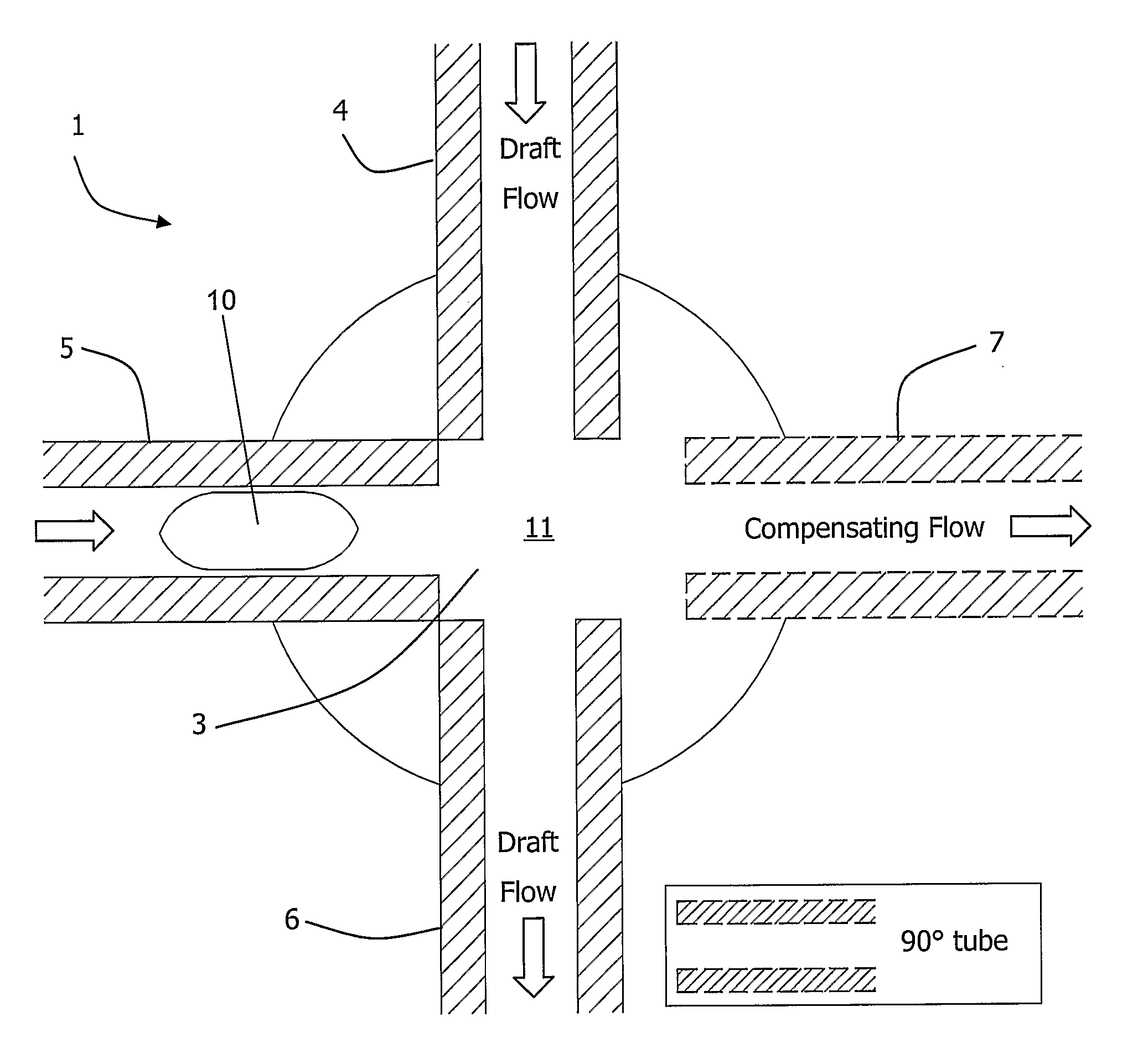
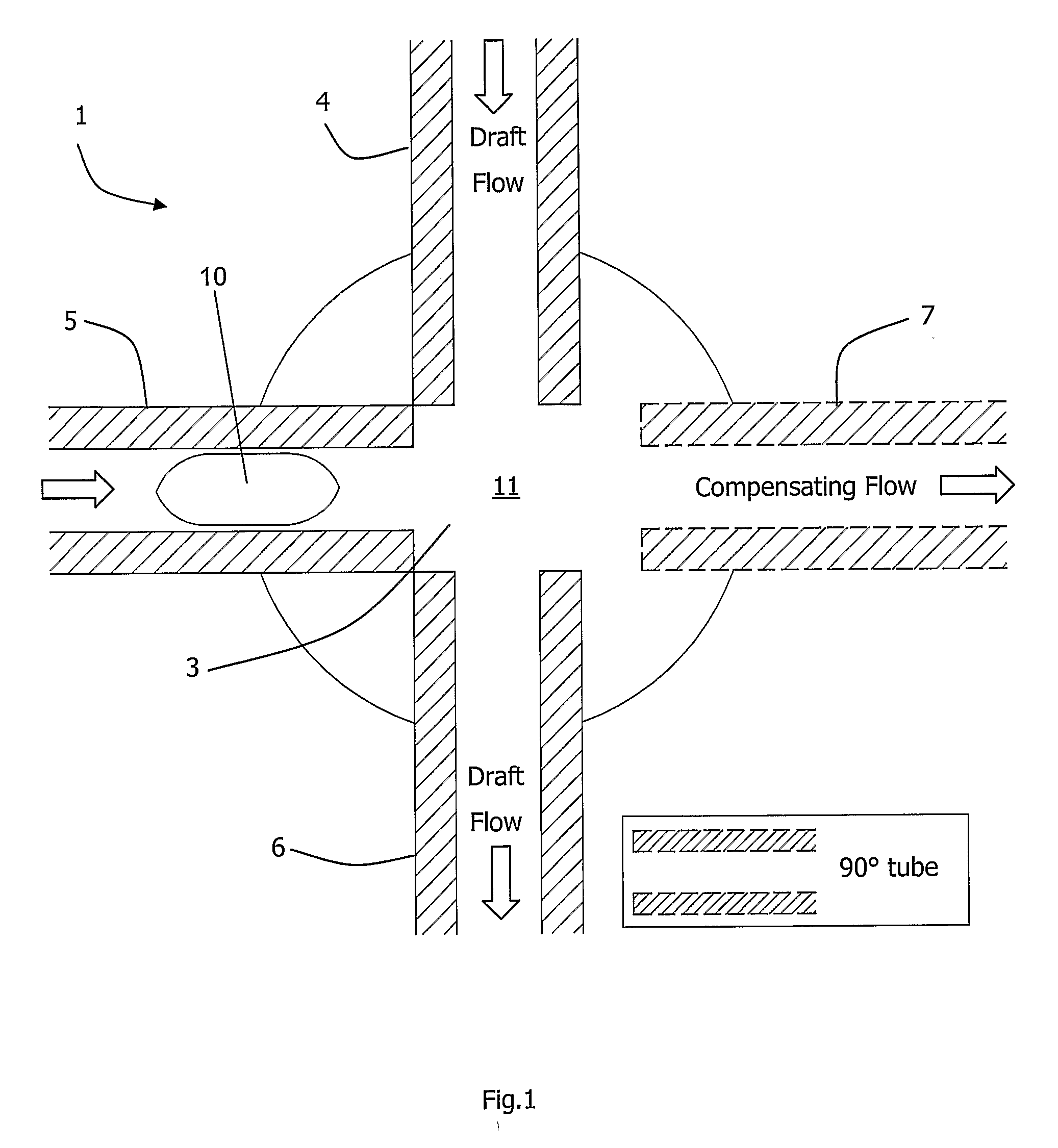
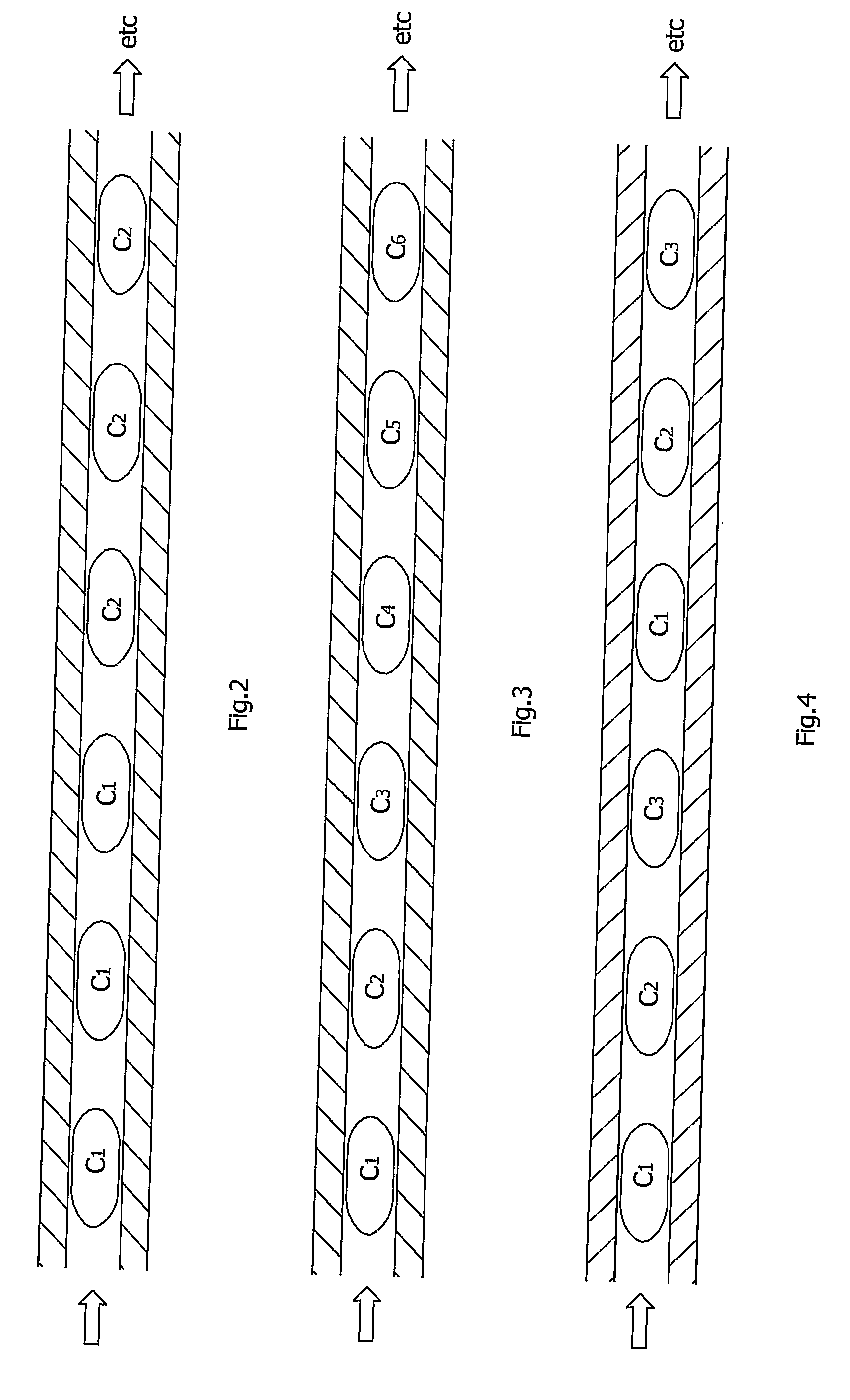
[0054]If liquid droplets are added to a tube or channel at different axial locations then the flow rate and velocity would increase in the flow direction, giving an undesirable summing of flow rates when queuing a number of droplets. To overcome this, equal volumes of liquid are added and subtracted simultaneously to keep the axial velocity in the queuing tube constant. A droplet network has bridges such that wherever a droplet is added to a draft flow excess carrier liquid (silicone oil) is removed via a compensating port. An aqueous phase entering from an inlet port will be delivered to an exit port, likewise for an aqueous phase arriving at an upper inlet port. By this means aqueous droplets can be introduced into the draft stream and delivered straight through all of the downstream bridges. In a single device, with steady inlet flows, a queue of droplets can be formed and delivered. Furthermore, a downstream segmenter can then be used to break a stream of droplets into droplets ...


PUM

PropertyMeasurementUnit
angleaaaaaaaaaa
diameteraaaaaaaaaa
diameteraaaaaaaaaa

Abstract

A multi-port liquid bridge (1) adds aqueous phase droplets (10) in an enveloping oil phase carrier liquid (11) to a draft channel (4, 6). A chamber (3) links four ports, and it is permanently full of oil (11) when in use. Oil phase is fed in a draft flow from an inlet port (4) and exits through a draft exit port (6) and a compensating flow port (7). The oil carrier and the sample droplets (3) (“aqueous phase”) flow through the inlet port (5) with an equivalent fluid flow subtracted through the compensating port (7). The ports of the bridge (1) are formed by the ends of capillaries held in position in plastics housings. The phases are density matched to create an environment where gravitational forces are negligible. This results in droplets (10) adopting spherical forms when suspended from capillary tube tips. Furthermore, the equality of mass flow is equal to the equality of volume flow. The phase of the inlet flow (from the droplet inlet port (5) and the draft inlet port (4) is used to determine the outlet port (6) flow phase.

Description

FIELD OF THE INVENTION[0001]The invention relates to control of flow of small discrete quantities of liquids (“droplets”) at the microfluidic scale.PRIOR ART DISCUSSION[0002]There are many applications emerging for the use of flowing liquid droplets for uses such as chemical reactors. The liquid droplets may be controlled in such a way that they are separated from one another by an immiscible carrier oil which also wets the inner channel or tube surface. The droplets are thereby completely wrapped by the oil phase and any chemical interaction with the surface, including carryover and cross-contamination between droplets is eliminated.[0003]It is known to provide droplets by, for example, segmenting a single phase homogeneous droplet into multiple smaller droplets of the same composition.[0004]However the art provides little guidance for controlling flow of multiple droplets, particularly where droplets contain different chemical compositions. WO2005 / 002730 describes a microfluidic d...

Claims


Application Information

Patent Timeline
Patent Type & Authority Applications(United States)
IPC IPC(8): C12Q1/68B01L3/00G01N1/00
CPCB01F13/0071B01F15/0201B01F15/0232B01L3/5025Y10T436/25B01L2200/0673B01L2300/0829B01L2400/0487B01J19/0046B01L3/502784B01J2219/00353B01J2219/00479B01J2219/00313B01J2219/00587B01J2219/00608B01F33/3021B01F35/71B01F35/7172
Inventor DAVIES, MARKDALTON, TARAGARVEY, JULIECURRAN, KIERANCURTIN, DAMIAN
Owner STOKES BIO LTD
Why Eureka
Try Eureka