Injection Device

a technology of injection device and syringe, which is applied in the direction of intravenous device, medical syringe, syringe, etc., can solve the problems of affecting so as to reduce the exposure to contaminants, avoid syringe movement, and ensure the effect of syringe movemen

Inactive Publication Date: 2010-01-21
NOVO NORDISK AS
View PDF99 Cites 25 Cited by
  • Summary
  • Abstract
  • Description
  • Claims
  • Application Information

AI Technical Summary

Benefits of technology

[0018]According to such a configuration, a prolongation or reduction of the stroke of the injection button compared to the stroke of the piston rod may be obtained. Further, as this configuration implies a change in the rate of rotation of the dose setting member for a given dose to be injected, a dose scale reading with a different layout may be obtained. In this way, a scale reading with increased distance between consecutive numbers may be obtained, which provides the possibility of increasing the font size of the labels of the scale reading. Also, this configuration provides the possibility of fine tuning the gearing ratio, if the injection device is so configured.
[0022]According to a fifth aspect of the invention, the rotational coupling mechanism comprises an incremental feedback mechanism providing incremental clicks during dose setting corresponding to dose volume. This aspect provides an easy adjustment of the rotational movement of the dose setting drum for each click, relatively to the housing part. In combination with the third aspect, an increase or a decrease of distance between the numbers on the dose setting drum or dose setting scale and thus the rotation for each click can be varied by choosing a specific pitch of the thread of the housing which engages the thread of the coupling member. By varying the inclination of the track along the extension of the track, it is possible to vary the rotation per click in a nonlinear way.
[0028]The term “housing” according to instant invention shall preferably mean an exterior housing (“main housing”, “body”, “shell”) or interior housing (“inner body”, “insert”) having internal and external threads. The housing may be designed to enable the safe, correct, and comfortable handling of the drug delivery device or any of its mechanisms. Usually, it is designed to house, fix, protect, guide, and / or engage with any of the inner components of the drug delivery device (e.g., the drive mechanism, cartridge, plunger, piston rod) by limiting the exposure to contaminants, such as liquid, dust, dirt etc. In general, the housing may be unitary or a multipart component of tubular or non-tubular shape. Usually, the exterior housing serves to house a cartridge from which a number of doses of a medicinal product may by dispensed. However, a cartridge may be directly coupled to the housing so as to be partly or fully external to the housing.

Problems solved by technology

This development is not quite favourable, as especially users having reduced finger strength have their difficulties in pressing the injection button, a problem that is further increased when still thinner needles are used to reduce the pain by injection.
Also with quite small movements of the button it is difficult to feel whether the button is moved at all and by injection of one unit from a 3 ml ampoule the piston and consequently the injection button has to be moved only about 0.1 mm.
However, by this kind of gearing relative large surfaces are sliding over each other so that most of the transformed force is lost due to friction between the sliding surfaces.
A disadvantage by this construction is that the teeth of the racks and gearwheels alternating have to be brought in and out of engagement with each other with the inherit danger of clashing.
Although broadly being considered state of the art, the injection device disclosed in U.S. Pat. No. 6,663,602 presents important mechanical constraints due to the construction principle of the linear gearing system which acts during dosing.
As the gear is an integrated part of the construction and as the gear can only be designed to certain transmission ratios, the gear implies important constraints on the obtainable ratio of movement of the injection button relative to the movement of the piston.
Due to the direct proportionality between the movement of the piston rod and the administered dose of medication, the same syringe can not easily be adapted to different medications.
Although adaptation is possible by changing the transmission ratio of the linear gear, this solution will in general be very complex and imply a complete redesign of the syringe.

Method used


Image

  • Injection Device
  • Injection Device
  • Injection Device

Examples


Embodiment Construction

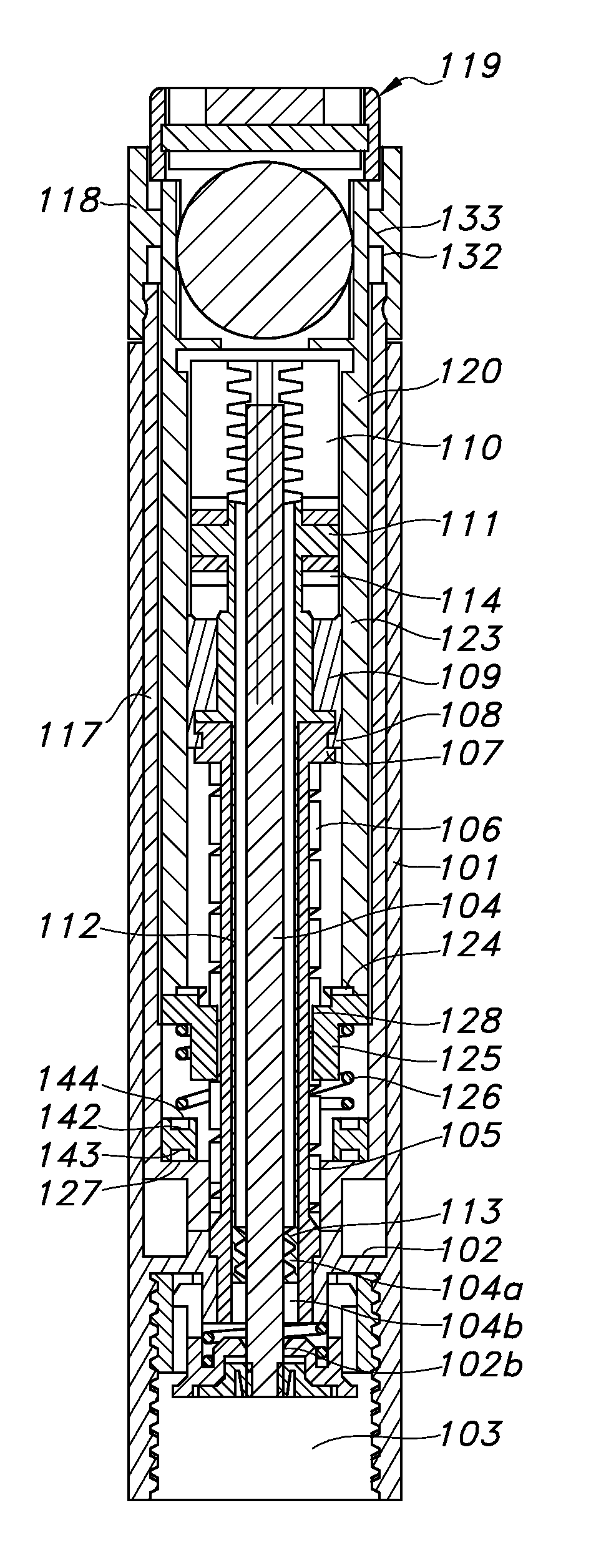
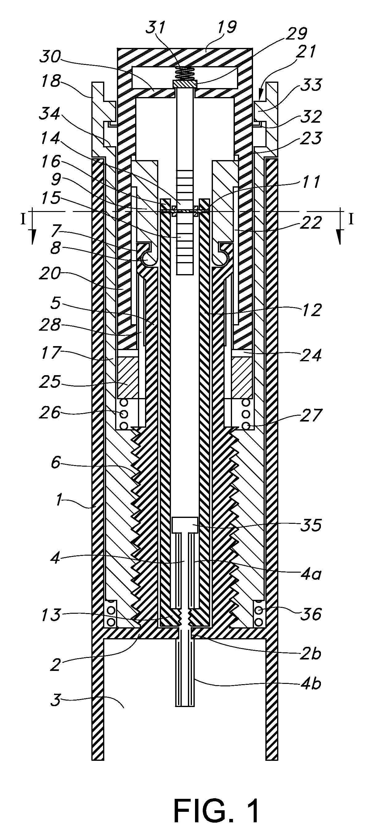
[0044]The device shown in the appended drawings is shown as an injector pen, which pen has an elongated body with a central axis. However, other forms are within the scope of the invention.

[0045]In the device shown in FIG. 1 an elongated cylindrical housing 1 has a partitioning wall 2 which divides the housing in a compartment containing a dose setting mechanism and a compartment 3 designed for the accommodation of a not shown ampoule. The partitioning wall 2 is provided with an opening extending there through. Alternatively, the wall may be replaced by an insert which is secured against rotational and axial motion with respect to the main structure of the housing 1, the opening being formed in said insert. A piston rod 4 having a first thread 4a and an additional longitudinally extending track 4b formed in or on the piston rod 4, extends through the opening 2b, which is provided with one or more ribs which mates and engages the additional longitudinal extending track 4b.

[0046]In a...


PUM


Abstract

An injection device for injection of set doses of medicine from a cartridge has a nut that is screwed up along a threaded piston rod during a dose setting operation. The nut is screwed along the piston rod by rotating a dose setting member. A rotational coupling mechanism includes an axially displaceable coupling member which is rotated as a function of axial displacement. During dose setting, the nut is allowed to rotate relative to the coupling member. During injection, the coupling member is rotationally locked to the nut. This provides a dose setting and injection mechanism wherein the nut member is both rotated during dose setting and during injection.

Description

CROSS-REFERENCE TO RELATED APPLICATIONS[0001]This application is a Continuation of copending U.S. application Ser. No. 11 / 911,871 filed Oct. 18, 2007 which is a 35 U.S.C. §371 national stage application of International Patent Application PCT / EP2006 / 061748 (published as WO 2006 / 114396), filed Apr. 21, 2006, which claimed priority of Danish Patent Application PA 2005 00589, filed Apr. 24, 2005; this application further claims priority under 35 U.S.C. §119 of U.S. Provisional Application 60 / 676,713, filed May 2, 2005.[0002]The present invention relates to syringes having a piston drive element for engaging and moving a piston within a medication cartridge, by which a dose can be set by rotating a nut along the piston drive element during dose setting, and wherein a set dose can be expelled by driving the nut to its initial position.BACKGROUND OF THE INVENTION[0003]An almost classic pen which adopts the above described dose setting and injecting scheme is described in EP 327 910.[0004]...

Claims


Application Information

Patent Timeline
Patent Type & Authority Applications(United States)
IPC IPC(8): A61M5/315
CPCA61M5/31541A61M5/31551A61M5/31556A61M5/31558A61M5/3156A61M2005/3152A61M5/31573A61M5/31575A61M5/3158A61M5/31585A61M5/31561
Inventor GLEJBOL, KRISTIANLINNEBJERG, STEVENMOLLER, CLAUS SCHMIDTHANSEN, MICHAEL EJSTRUP
Owner NOVO NORDISK AS
Why Eureka
Try Eureka