Horizontal-tube sedimentation-separation apparatus

a sedimentation-separation apparatus and horizontal tube technology, applied in sedimentation settling tanks, separation processes, liquid displacement, etc., can solve the problems of reversible sedimentation, water state variation, harmful suspension sedimentation, etc., and achieve the effect of gradual decrease of width

Active Publication Date: 2010-01-28
ZHUHAI 9TONE WATER DEV
View PDF11 Cites 4 Cited by
  • Summary
  • Abstract
  • Description
  • Claims
  • Application Information

AI Technical Summary

Benefits of technology

[0013]As a preferable design, an upper compensating body comprising multiple groups of inclined plates with their width gradually increased from top to bottom is set in the upper side of main body. Its cross-section mixes with the main body cross-section to form an inverted right-angled trapezoid. The static fluid regions between inclined plates connect with vertical sedimentary slide path located outside. This design eliminates the upper dead zone and the matched sedimentation tank could have inverted right-angled trapezoid cross-section, which is suitable for construction.
[0014]As a preferable design, a lower compensating body...

Problems solved by technology

Firstly, flowing water needs to change its direction when through the inclined tube or inclined plate (same-directional, counter-directional), thus leads to water state variation and is harmful to the suspension sedimentation.
Secondly, the process of water flowing through inclined tube or inclined plate has a washing and disturbing effect on sedimentary suspension, which would probably be re-agitate...

Method used


Image

  • Horizontal-tube sedimentation-separation apparatus
  • Horizontal-tube sedimentation-separation apparatus
  • Horizontal-tube sedimentation-separation apparatus

Examples


first embodiment

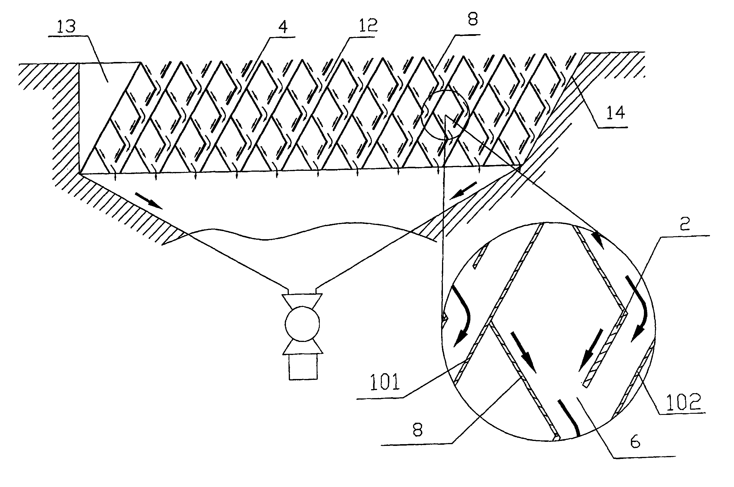
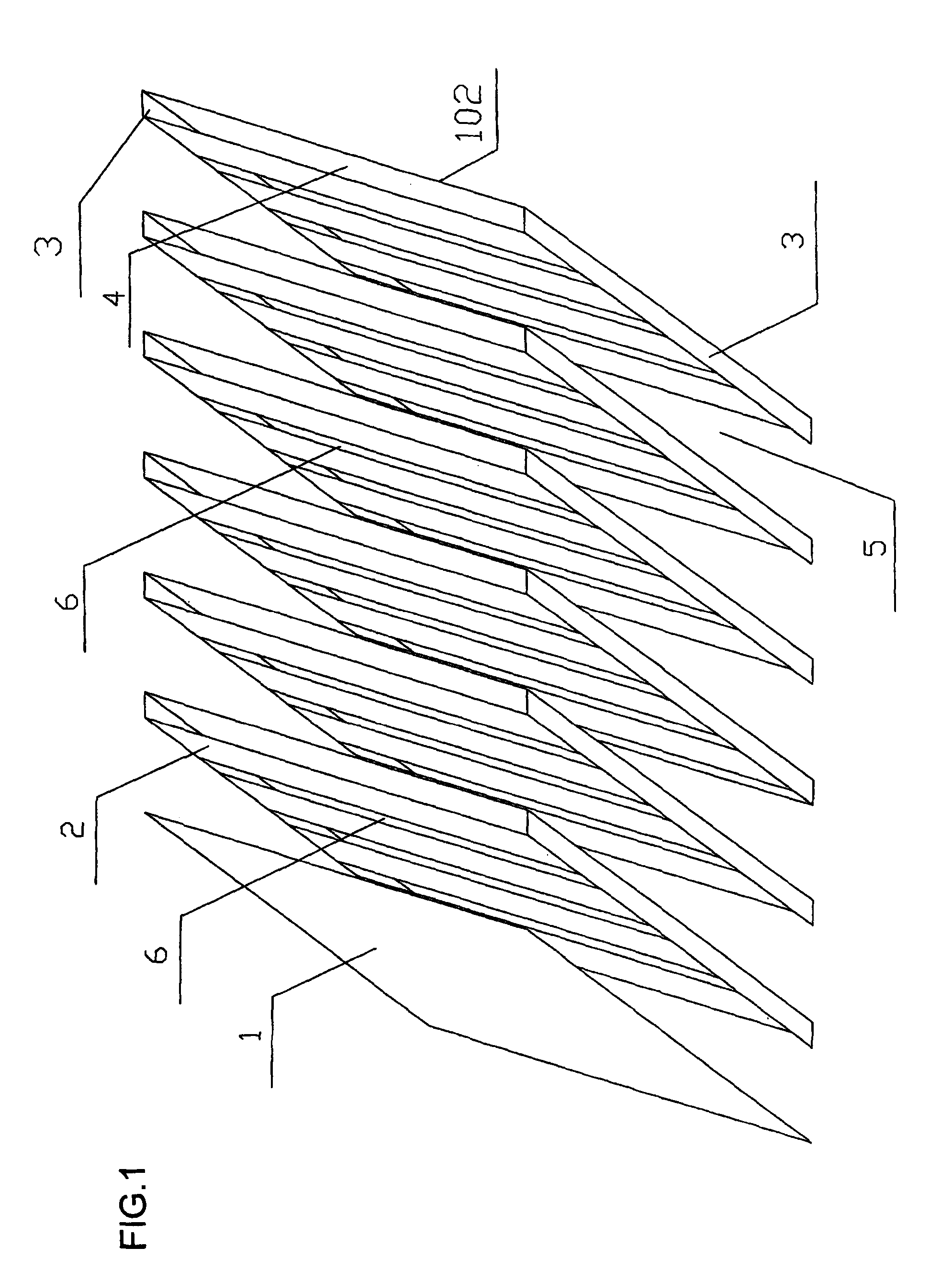
[0034] As described in FIG. 1, this horizontal-tube sedimentation-separation apparatus incorporates multiple parallel inclined plates 1, and between adjacent inclined plates 1 are isolated plates 2 which are parallel to inclined plate. Baffles 3 that are vertical to the water flowing direction are set in front of and back of the bottom of isolated plate 2, which blocks water flowing under the isolated plate 2, thereby forming a static fluid region 4. The static fluid region 4 together with the flowing region 5 up the isolated plate forms a working unit. Multiple sludge-disposal paths are set on isolated plate 2 from top to bottom, and each of them is designed as a long-tank 6 extended in the direction of water flow.

second embodiment

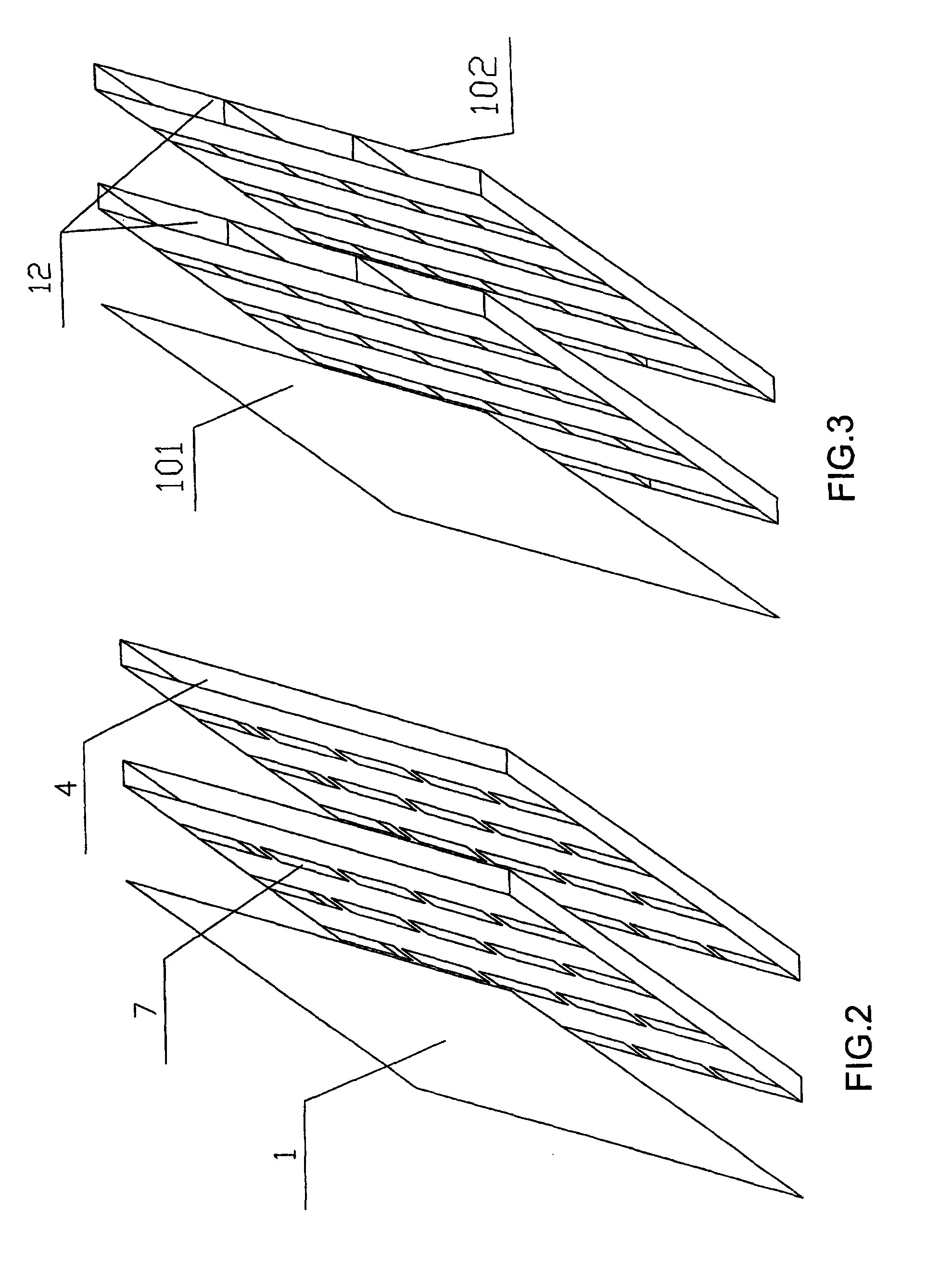
[0035] As described in FIG. 2, each line of sludge-disposal path consists of multiple sludge-disposal ports 7 distributed along the direction of water flow. Other components and structures are the same as described in first embodiment.

[0036]Third embodiment: As described in FIG. 3, there are four pieces of baffle 3. Other components and structures are the same as described in first embodiment. The front and back baffles tightly connect with isolated plate and lower inclined plate, thus forming static fluid region. Intermediate baffle plays a supporting and reinforcing role to prevent deformation of and the closing between isolated plate and lower inclined plate.

fourth embodiment

[0037] As described in FIG. 4 and FIG. 5, between isolated plate 2 and its upper inclined plate 101 is the flat supporting plate 8, whose upper end connects with upper inclined plate 101 and its lower end connects with and also flush with the bottom margin of long-tank 6. Other components and structures are the same as described in first embodiment.

[0038]The sludge-disposal path is designed as a long-tank 6 that extended in the direction of water flow. The flat supporting plate 8 is of a complete rectangle shape. The sludge-disposal path is designed as a long-tank 6 that extended in the direction of water flow, and each long-tank requires a complete and rectangle flat supporting plate 8 to match as described in FIG. 4.

[0039]Fifth embodiment: As described in FIG. 5, the sludge-disposal path consists of multiple sludge-disposal ports 7 distributed in the direction of water flow. Each sludge-disposal port 7 requires a piece of flat supporting plate 8 to match, thus the sedimentation wo...


PUM

PropertyMeasurementUnit
Angleaaaaaaaaaa
Widthaaaaaaaaaa

Abstract

A brief abstract of the technical disclosure in the specification must commence on a separate sheet, preferably following the claims, under the heading “Abstract of the Disclosure.” The purpose of the abstract is to enable the Patent and Trademark Office and the public generally to determine quickly from a cursory inspection the nature and gist of the technical disclosure. The abstract shall not be used for interpreting the scope of the claims.
Therefore, any statements made relating to the abstract are not intended to limit the claims in any manner and should not be interpreted as limiting the claims in any manner.
The embodiments of the invention described herein above in the context of the preferred embodiments are not to be taken as limiting the embodiments of the invention to all of the provided details thereof, since modifications and variations thereof may be made without departing from the spirit and scope of the embodiments of the invention.

Description

CONTINUING APPLICATION DATA[0001]This application is a Continuation-In-Part application of International Patent Application No. PCT / CN2007 / 003313, filed on Nov. 23, 2007, which claims priority from People's Republic of China Patent Application No. 200610123752.2, filed on Nov. 24, 2006. International Patent Application No. PCT / CN2007 / 003313 was pending as of the filing date of this application. The United States was an elected state in International Patent Application No. PCT / CN2007 / 003313.FIELD OF THE INVENTION[0002]The present invention relates to a wastewater treatment equipment. In particular, it relates to a horizontal-tube sedimentation-separation apparatus.BACKGROUND OF THE INVENTION[0003]Based on the shallow-basin theory that was brought up by American scientist Hazen in 1904, inclined plate sedimentation tank, inclined tube sedimentation tank and labyrinth sedimentation tank were successively developed, and their structure were designed as much close as an ideal sedimentati...

Claims


Application Information

Patent Timeline
IPC IPC(8): B01D21/02
CPCB01D21/0051B01D21/0075B01D21/0063
Inventor ZHANG, LIANGCHUNZHANG, JIANGUO
Owner ZHUHAI 9TONE WATER DEV
Why Eureka
Try Eureka