Neutron detector

a neutron detector and detector technology, applied in the field of neutron detectors, can solve the problems of not being able to provide a directional estimate in three-dimensional space, the performance of most neutron detectors is well below the theoretical limit, and the performance of most neutron detectors is not optimal for their intended use, so as to improve the discrimination capability and improve the use efficiency of moderator materials.

Inactive Publication Date: 2010-01-28
MATERIALS INNOVATION INC
View PDF54 Cites 38 Cited by
  • Summary
  • Abstract
  • Description
  • Claims
  • Application Information

AI Technical Summary

Benefits of technology

[0041]Objects of the present invention include the following: providing a more efficient neutron detector; providing a neutron detector that makes more efficient use of moderator materials; providing a radiation detector with improved discrimination capabilities; providing a neutron detector capable of obtaining information about the energy spectrum of neutrons it detects; providing a neutron detector capable of determining the isotope(s) from which neutrons have been detected, even when significant shielding is present that modifies the energy spectrum of the neutrons that reach the detector from the source; and providing directional information about neutrons reaching the detector. These and other objects and advantages of the invention will become apparent from consideration of the following specification, read in conjunction with the drawings.
[0042]According to one aspect of the invention, an apparatus for detecting neutrons comprises: a volume of neutron moderating material having a selected outside surface; and, four groups of neutron detecting elements, each group comprising at least one detecting element, each of said groups disposed at a substantially different distance from said selected outside surface so that each of said groups is separated from said selected surface by a substantially different areal density of said moderating material.
[0043]According to another aspect of the invention, an apparatus for detecting fissile materials comprises: a particle generator configured to provide particles capable of inducing neutron emission from at least one fissile material; a volume of neutron moderating material having a selected outside surface; and, four groups of neutron detecting elements, each group comprising at least one detecting element, each of said groups disposed at a substantially different distance from said selected outside surface so that each of said groups is separated from said selected surface by a substantially different areal density of said moderating material.

Problems solved by technology

In general, most neutron detectors do not perform in an optimal way for their intended use and the performance of most neutron detectors is well below that of theoretical limits.
Both the Penn and Byrd devices can produce an estimate of the radial / azimuthal angle of neutron travel but do not produce a polar angle, precluding an estimate of source location in three-dimensional space.
The Schulte device is bidirectional and does not provide a directional estimate in three-dimensional space.
Although this approach does yield high confidence in the direction of travel of a neutron, it does so primarily for low energy neutrons (e.g. cold and approximately thermal neutrons) and results in most neutrons coming from a direction other than from a narrow angular range being lost completely to the detector rather than being differentiated on the basis of their direction of travel.
As most security-related neutron detection applications require detecting only a small increase in neutron fluence through a detector, maximizing neutron detection efficiency is quite important and a high loss rate of neutrons reaching the detector to fates other than detection is undesirable.
The disclosed device does not yield spectroscopic information, only a measurement of fast neutrons.
The device consists of alternating layers of scintillating material and optically transparent hydrogenous neutron moderator material, with the layers “dimensioned to optimize spectroscopic detection efficiency.” However, it is clear that the device described does not actually produce an estimate of the neutron energy spectrum, but instead is “spectroscopic” only in the sense that it detects neutrons between 0.5 and 14 MeV and does not detect neutrons of lesser energy.
Hutchinson et al. do not disclose any directional or spectroscopic neutron capability.
As designed and operated, the Model 2442 does not provide information about neutron direction (neutrons are assumed to originate in the sample being measured, which is located inside the cavity in the device) or neutron energy.

Method used


Image

  • Neutron detector
  • Neutron detector
  • Neutron detector

Examples


example 1

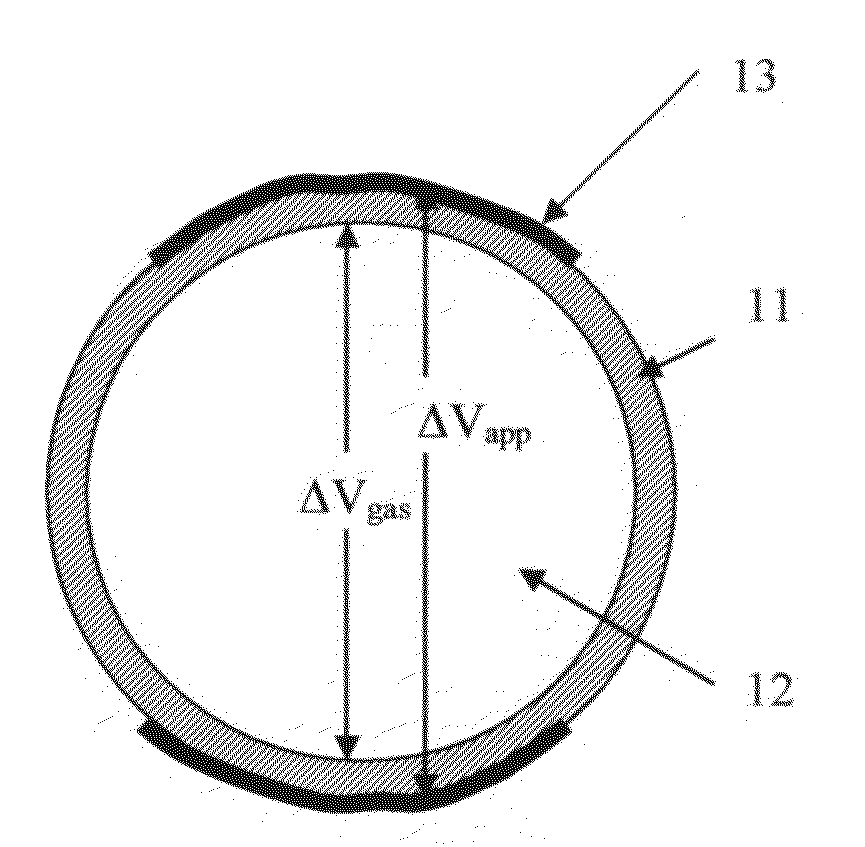
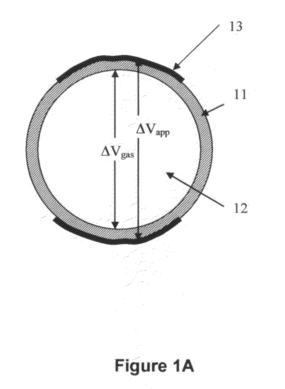
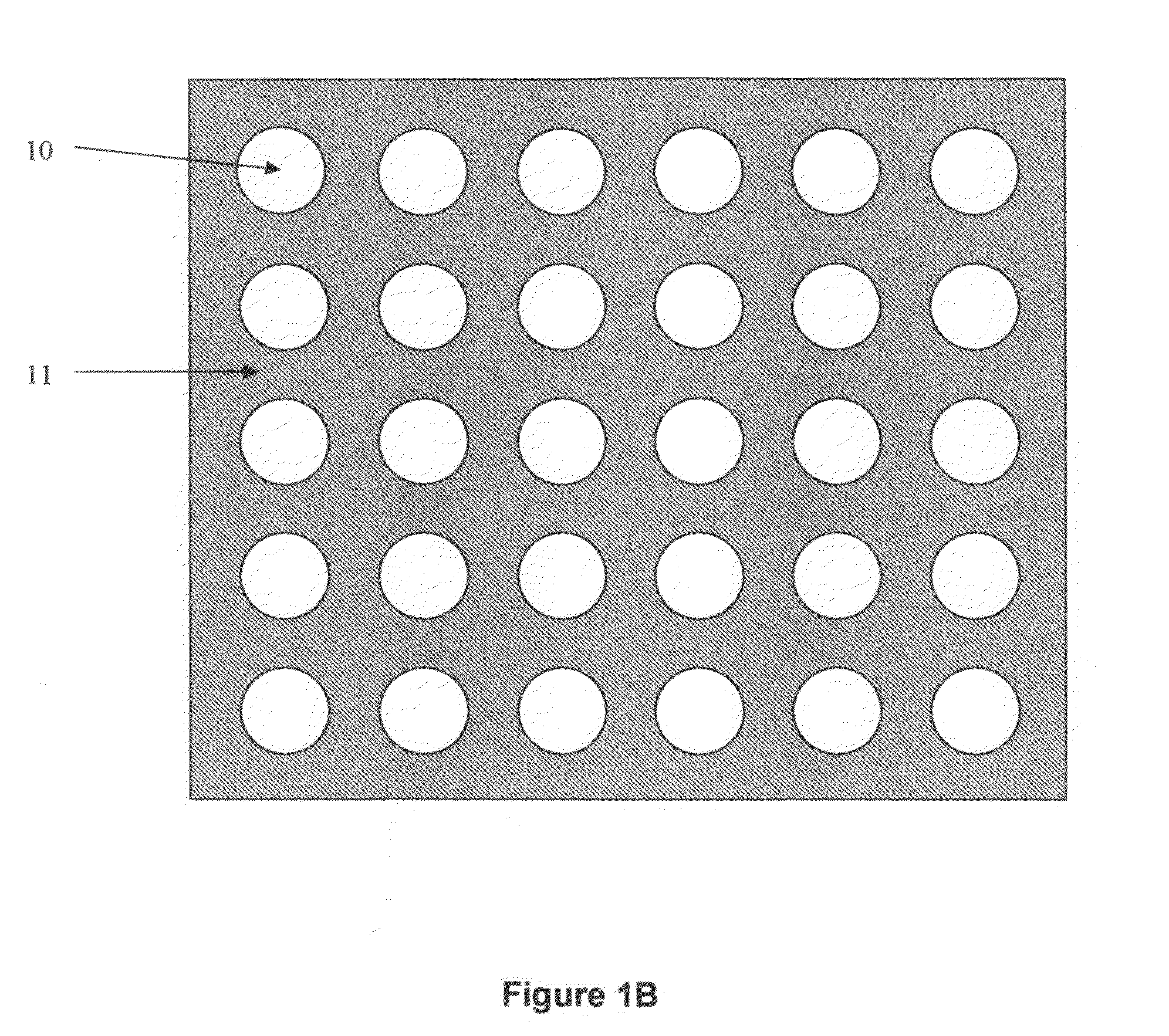
[0071]Applicants constructed a number of dielectric sensors consisting of gas-filled spherical balloons 10 (i.e. having an outer shell 11 and a hollow interior 12 filled with gas). Based on calculations of electrical conductivity, particle transport and energy deposition, and long-term gas retention, the sensors had an outer diameter of 7 mm with 200 μm thick glass walls 11. The interior 12 of each sensor was filled with a gas mixture consisting of 3×10⁵ Pa 3He and 5×10⁵ Pa Ar. This combination of gas composition, gas pressure, and sensor size was sufficient for most 3He neutron capture events to deposit much or all of the energy released from the neutron capture reaction (in the form of energetic reaction products) in the sensor gas. Simultaneously, the combination of sensor size and gas pressure or density was low enough such that most gamma-induced electrons produced only minimal energy deposition in a sensor.

[0072]The glass consisted of a modified fused silica with a low gas dif...

example 2

[0078]FIG. 2 shows the neutron detection efficiency for neutrons emitted by plutonium (via spontaneous fission) for three cases. In all cases, the detector(s) are held within a 100 cm wide×100 cm high×25 cm thick HDPE matrix material, with an additional 10 cm thick HDPE reflector located on each side of the detector to improve neutron detection efficiency (making the entire structure 120 cm×120 cm×25 cm). The neutron detection efficiency is defined as the likelihood that a neutron entering the device will be captured in (and therefore detected by) a neutron detecting element (e.g. a dielectric sensor) in the device. In this example, the plutonium-emitted neutrons are assumed to enter the detector uniformly across the 100 cm×100 cm surface perpendicularly. In all four cases, the detectors detect a neutron when the neutron is captured by a 3He atom, causing an atomic reaction that releases 764 keV of energy and is easily detectable. The three cases are as follows:

[0079]Case #1 is a de...

example 3

[0083]A device with a substantially planar geometry can be created and used to preferentially detect neutrons entering the device in a perpendicular direction. For an application such as scanning a vehicle for the presence of special nuclear material (SNM), a device with a planar surface area of 0.2 m2 or more and a thickness of 20 cm or greater is preferred. In this example, the bulk of the device consists of a material (e.g. HDPE) that is effective at moderating fast neutrons (e.g. neutrons with energies of 100 keV or more). Neutron-detecting balloons are interspersed within the material in such a way that their collective neutron detection efficiency is optimized. For a device containing 13 layers of neutron-detecting balloons of 6.6 mm inner diameter with 3×10⁵ Pa 3He gas filling and 0.72 cm center-to-center spacing between the balloons in a single layer, preferred depths of the layers into the device from the surface facing the vehicle to be scanned are 0.35, 1.5, 2.5, 3.5, 4.5...


PUM

PropertyMeasurementUnit
energyaaaaaaaaaa
energyaaaaaaaaaa
energyaaaaaaaaaa

Abstract

A neutron detector has a volume of neutron moderating material and a plurality of individual neutron sensing elements dispersed at selected locations throughout the moderator, and particularly arranged so that some of the detecting elements are closer to the surface of the moderator assembly and others are more deeply embedded. The arrangement captures some thermalized neutrons that might otherwise be scattered away from a single, centrally located detector element. Different geometrical arrangements may be used while preserving its fundamental characteristics. Different types of neutron sensing elements may be used, which may operate on any of a number of physical principles to perform the function of sensing a neutron, either by a capture or a scattering reaction, and converting that reaction to a detectable signal. High detection efficiency, an ability to acquire spectral information, and directional sensitivity may be obtained.

Description

CROSS-REFERENCE TO RELATED APPLICATION[0001]This application is a Continuation-in-Part of U.S. patent application Ser. No. 11 / 820,261 entitled Neutron Detector, filed by the present inventors on Jun. 19, 2007; it is also related to U.S. patent application Ser. No. 11 / 820,346 entitled Neutron Detector, filed by the present inventors on Jun. 19, 2007, now issued as U.S. Pat. No. 7,514,694; it further contains material disclosed in part in U.S. patent application No. ______ entitled Neutron Detector filed by the present inventors on even date herewith. The entire disclosures of each of the foregoing documents are incorporated herein in their entirety.STATEMENT REGARDING FEDERALLY SPONSORED RESEARCH[0002]The United States Government has rights in this invention pursuant to contract No. DE-AC05-00OR22725 between the United States Department of Energy and UT-Battelle, LLC. and Agreement No. HSHQPA-05-9-00047 awarded by the U. S. Department of Homeland Security to Material Innovations, Inc...

Claims


Application Information

Patent Timeline
Patent Type & Authority Applications(United States)
IPC IPC(8): G01N23/22G01T3/06G01T3/00
CPCH01J47/1255G01T3/00
Inventor STEPHAN, ANDREW C.JARDRET, VINCENT D.
Owner MATERIALS INNOVATION INC
Why Eureka
Try Eureka