Potential measurement apparatus and image forming apparatus

a technology of image forming apparatus and measurement apparatus, which is applied in the direction of resistance/reactance/impedence, instruments, electrographic processes, etc., can solve the problems of poor responsiveness of known potential measurement apparatus, inability to adapt to high-speed measurements, and coarse so as to improve accuracy and spatial resolution of measurement, the effect of quick respons

Inactive Publication Date: 2010-01-28
CANON KK
View PDF0 Cites 39 Cited by
  • Summary
  • Abstract
  • Description
  • Claims
  • Application Information

AI Technical Summary

Benefits of technology

[0021]The potential measurement apparatus of the present invention arithmetically processes a plurality of outcomes of detection of the signal representing the fundamental period, the signal representing the double period of the fundamental period and the information on the capacitance and measures the surface potential of the object of measurement without depending on the distance between the objec

Problems solved by technology

However, known potential measurement apparatus are poorly responsive and are not adapted to high-speed measurements because the apparatus employ a high voltage power source for the purpose of suppressing the dependency on the distance between the object of measurement and the detection electrode and it is subjected to feedback control.
Additionally

Method used


Image

  • Potential measurement apparatus and image forming apparatus
  • Potential measurement apparatus and image forming apparatus
  • Potential measurement apparatus and image forming apparatus

Examples


first embodiment

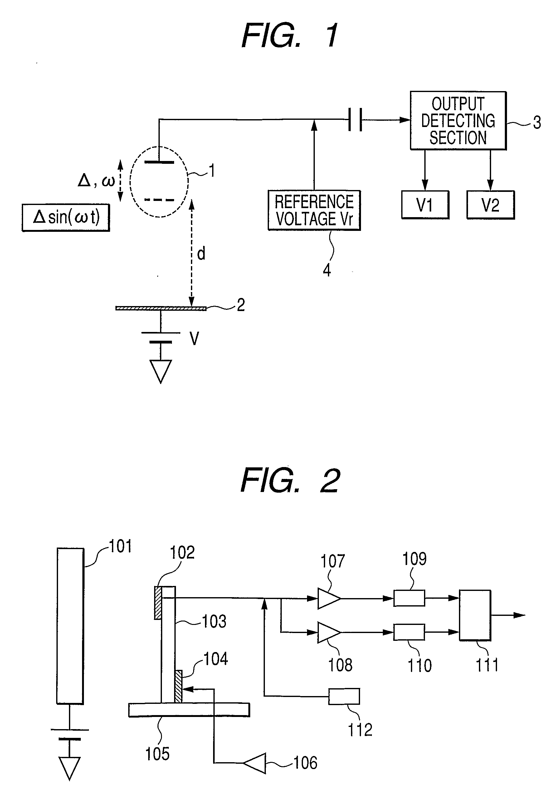
[0040]FIG. 2 is a schematic circuit diagram of the first embodiment, illustrating the configuration thereof in greater detail. Again, an electric charge is induced at the detection electrode 102 by electrostatic induction from the object of measurement 101. In FIG. 2, a piezoelectric device 104 is applied to a base position of cantilever 103 carrying the detection electrode 102 in order to drive the detection electrode 102 to oscillate with a predetermined constant period. The base of the cantilever 103 is rigidly anchored to a stationary table 105. The piezoelectric device 104 is driven to operate by an oscillator 106.

[0041]With this arrangement, the oscillation of the cantilever 103 can be sustained by the resonance frequency and the detection electrode 102 can be stably driven with a predetermined constant frequency and a predetermined constant amplitude. The change in the electric current from the detection electrode 102 sorted by a fundamental frequency filter 107 and a second ...

third embodiment

[0050]Now, the present invention will be described below. This embodiment is an image forming apparatus using a potential measurement apparatus according to the present invention.

[0051]FIG. 5 is a schematic block diagram of the image forming apparatus of the third embodiment of the invention, illustrating the configuration thereof. As illustrated in FIG. 5, a charger 13 that can be controlled by a charger control unit 12, a potential measurement apparatus 14 according to the present invention, an exposure unit 15 and a developer supply unit 16 are arranged around a photosensitive drum 11. The mechanism for controlling the charged quantity of electricity of the photosensitive drum 11 is formed by the charger control unit 12, the charger 13 and the potential measurement apparatus 14 according to the present invention and the charger control unit 12 is connected to the charger 13, while the potential measurement apparatus 14 according to the present invention is connected to the charge...


PUM


Abstract

A potential measurement apparatus for measuring a surface potential of an object of measurement detects a change in electric charge induced at a detection electrode due to electrostatic induction by changing a distance between the detection electrode and the object of measurement in accordance with a predetermined period, using a neutral distance as reference, as a signal representing a change in electric current. The potential measurement apparatus includes a first detection unit for detecting a signal representing a fundamental period of the change in electric current and a signal representing a second harmonic period, a second detection unit for detecting information representing a capacitance between the detection electrode at the neutral distance and the object of measurement and an arithmetic unit for computationally obtaining information on the surface potential of the object of measurement, with eliminating an influence of the neutral distance and the capacitance, according to an outcome of detection of the first detection unit and an outcome of detection of the second detection unit.

Description

TECHNICAL FIELD[0001]The present invention relates to a potential measurement apparatus that can be used for measuring the surface potential and the charged quantity of electricity of an object of measurement by changing the distance between the detection electrode of the apparatus and the object of measurement and also to an image forming apparatus using the same.BACKGROUND ART[0002]The photosensitive drum surface of an image forming apparatus having a photosensitive drum and designed to form an image by electrophotography is required to be electrified so as to show an appropriate (typically uniform) potential distribution in any environment in order to constantly produce images of a stabilized quality. For this reason, a functional device for measuring the electric potential of the photosensitive drum surface by means of a potential measurement apparatus and feedback-controlling the potential of the photosensitive drum surface so as to keep the potential uniform, utilizing the out...

Claims


Application Information

Patent Timeline
IPC IPC(8): G01R27/26G01R1/02
CPCG01R29/12G03G15/5037G03G15/0266
Inventor KATO, KAZUHIKOOGAWA, TOSHIYUKIZAITSU, YOSHITAKAUSHIJIMA, TAKASHINOGUCHI, KAORUKANDORI, ATSUSHIHIROSE, FUTOSHI
Owner CANON KK
Why Eureka
Try Eureka