Lens optical system

a technology of optical system and large aperture, applied in the field of large aperture lens optical system, can solve the problems of difficult to secure excellent optical performance in the entire range of distance from the object, double gauss type optical system does not provide the high optical performance required for highly pixelized digital, etc., to achieve excellent image formation performance, excellent optical performance, excellent aberration correction performan

Inactive Publication Date: 2010-01-28
SAMSUNG ELECTRONICS CO LTD
View PDF1 Cites 31 Cited by
  • Summary
  • Abstract
  • Description
  • Claims
  • Application Information

AI Technical Summary

Benefits of technology

[0009]The present invention provides a lens optical system, which has the excellent optical performance required for a digital single lens reflex camera and the excellent image formation performance over the entire range of distance from an object. The lens optical system includes a large aperture lens having an excellent aberration correction performance.

Problems solved by technology

However, the double Gauss type optical system does not provide sufficiently high optical performance required for the highly pixelized digital single lens reflex camera.
However, when the method of correcting image plane movement is used in a large aperture lens having an aperture ratio of 1:1.2-1.5, longitudinal spherical aberration is significantly changed as the distance from the object is changed from infinity to a short distance, and thus it is difficult to secure an excellent optical performance in the entire range of distance from the object.

Method used


Image

  • Lens optical system
  • Lens optical system
  • Lens optical system

Examples


first embodiment

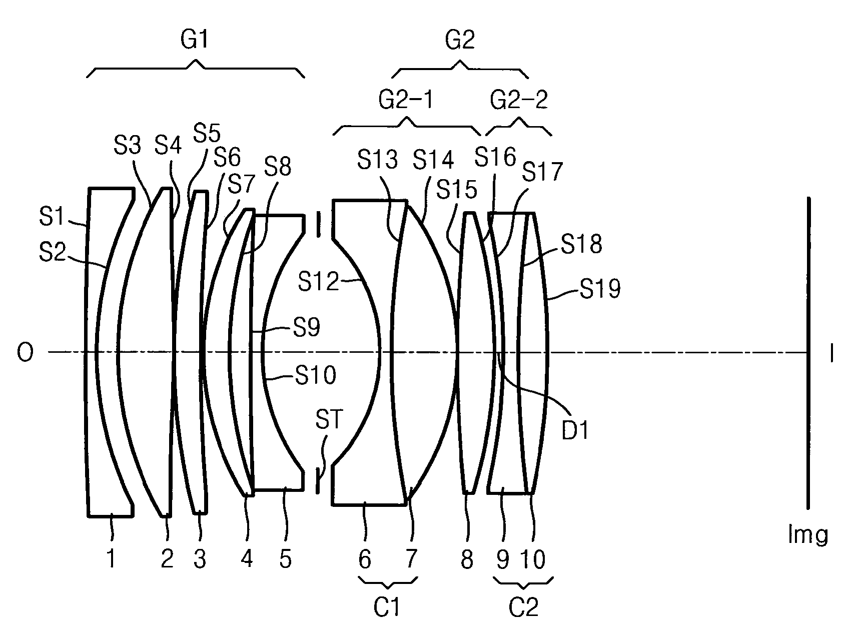
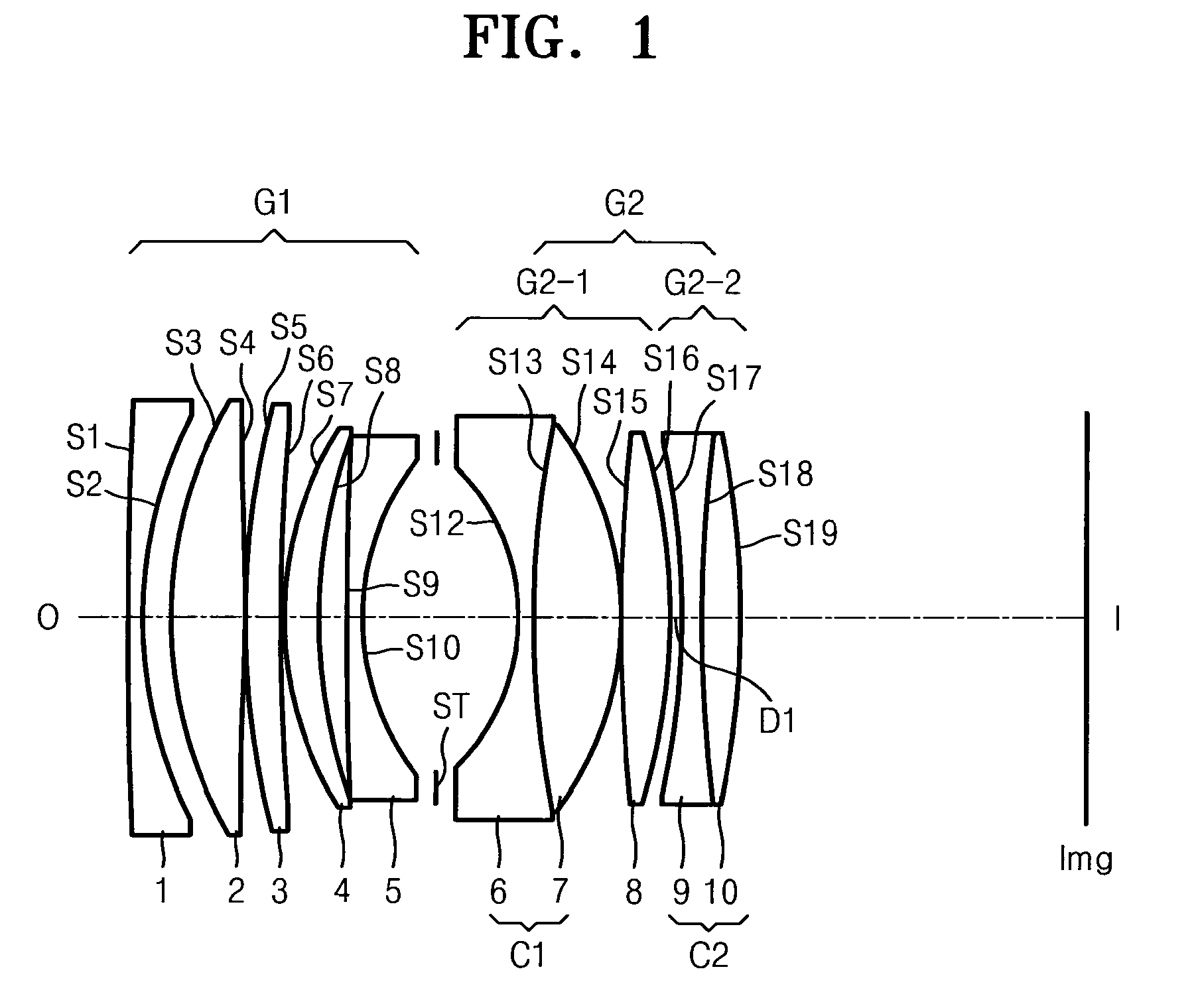
[0057]FIG. 1 illustrates the lens optical system according to the first embodiment of the present invention. The following design data corresponds to the lens optical system according to the first embodiment of the present invention.

f; 51.48 Fno; 1.20 2ω; 46.4°Lens sideRDnNdVdS11000.001.501.8051825.46S248.3083.14S345.9008.071.8340037.34S4−750.8120.20S583.3564.301.9036631.31S6386.1700.20S738.1513.801.9036631.31S860.0553.07S9614.9341.501.5814440.89S1027.0828.43STinfinity8.97S12−22.3591.501.7521125.05S1392.8619.681.8830040.8S14−35.0360.20S15163.9565.451.8061040.73S16*−61.423D1ASP:K: −1.000A: 1.44905e−006B: −3.20985e−010C: 9.95240−013D: 0S17−80.5672.001.7173629.5S18185.0274.501.8348142.72S19−80.66838.23lmg

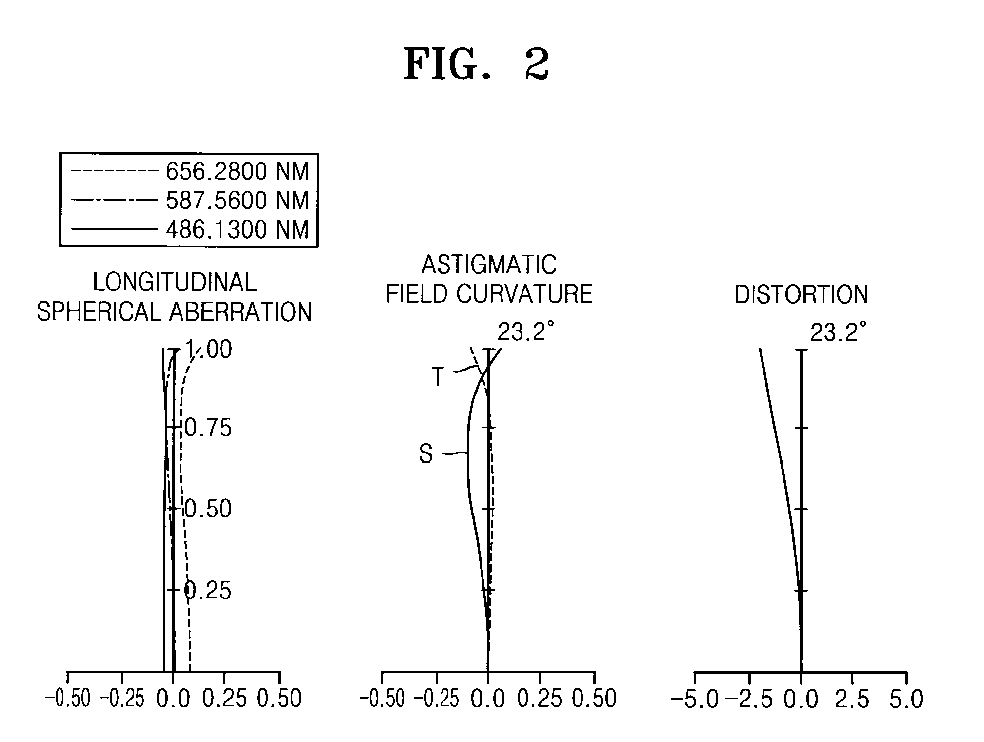
[0058]FIG. 2 illustrates longitudinal spherical aberration, astigmatic field curvature, and distortion of the lens optical system according to the first embodiment of the present invention. The longitudinal spherical aberration is illustrated as C-line and F-line based on Fraunhofer d-...

second embodiment

[0060]FIG. 4 illustrates the lens optical system according to the second embodiment of the present invention.

f; 52.00 Fno; 1.25 2ω; 46.1°Lens sideRDnNdVdS11000.001.501.8051825.46S252.6004.13S351.1528.071.8830040.8S4−183.2510.30S536.4105.031.8830040.8S684.3712.78S7−2090.9511.501.5638460.83S827.1988.00STinfinity12.42S10−26.4571.50S1147.9528.821.8830040.8S12*−49.5130.20ASP:K: −4.45356A: 3.05419e−007B: 8.26193e−010C: −1.60775e−012D: 0S131261.6305.601.8061040.73S14*−43.372D1ASP:K: −1.000A: −3.30636e−006B: 3.09637e−009C: −3.46198e−013D: 0S15−350.3611.501.7521125.05S1676.2864.151.8830040.8S17−242.63838.06img

[0061]FIG. 5 illustrates longitudinal spherical aberration, astigmatic field curvature, and distortion of the lens optical system according to the second embodiment of the present invention. Table 2 shows D1.

TABLE 2Distance from objectInfinity45 cmD11.269.19

third embodiment

[0062]FIG. 6 illustrates the lens optical system according to the third embodiment of the present invention.

f; 59.16 Fno; 1.35 2ω; 40.4°Lens sideRDnNdVdS1149.8551.501.8051825.46S246.2021.13S342.4367.531.8830040.8S4−2000.0000.43S535.8795.731.8340037.34S671.9683.44S7334.3052.401.5511549.52S825.2667.97STinfinity11.19S10−25.3961.67S1151.30911.601.8830040.8S12−53.5820.22S13169.7234.731.8061040.73S14*−54.377D1ASP:K: −1.000A: 1.301053e−006B: 2.435146e−010C: 2.334887e−013D: 0S17386.7043.011.8348142.72S18−1000.00038.36img

[0063]FIG. 7 illustrates longitudinal spherical aberration, astigmatic field curvature, and distortion of the lens optical system according to the third embodiment of the present invention. Table 3 shows D1.

TABLE 3Distance from objectInfinity45 cmD11.2010.5

[0064]Table 4 below shows that the lens optical systems according to the first to third embodiments satisfy the conditions of Inequalities 1, 2, and 3.

TABLE 4FirstSecondThirdembodimentembodimentembodimentInequality 11.341....


PUM


Abstract

Provided is a lens optical system, which includes (from object to image side) a first lens group having positive refractive power, a stop, and a second lens group having positive refractive power. The first lens group comprises a plurality of lenses among which there are a lens closest to the object side and a lens closest to the stop having negative refractive powers. The second lens group includes a front group and a rear group.

Description

CROSS-REFERENCE TO RELATED PATENT APPLICATION[0001]This application claims the benefit of Korean Patent Application No. 10-2008-0071229, filed on Jul. 22, 2008, in the Korean Intellectual Property Office, the disclosure of which is incorporated herein in its entirety by reference.BACKGROUND OF THE INVENTION[0002]1. Field of the Invention[0003]The present invention relates to a large aperture lens optical system.[0004]2. Description of the Related Art[0005]Recently, the demand for single lens reflex cameras has significantly increased. Much attention has been paid to digital single lens reflex cameras employing an image sensor, such as a charge coupled device (CCD) or a complementary metal-oxide semiconductor (CMOS), instead of film cameras. Digital single lens reflex cameras are highly pixelized according to the demand of users and the development of image sensor technology. Thus, an interchangeable lens used in digital single lens reflex cameras needs to have excellent optical perf...

Claims


Application Information

Patent Timeline
Patent Type & Authority Applications(United States)
IPC IPC(8): G02B9/08
CPCG02B9/08G02B15/00
Inventor HEU, MIN
Owner SAMSUNG ELECTRONICS CO LTD
Why Eureka
Try Eureka