X-Ray Scanners and X-Ray Sources Therefor

a technology of x-ray scanners and sources, applied in the field of x-ray scanners, can solve the problems of complex detection electronics, unacceptably high levels of artefacts, and high cost of measuring the energy of every single x-ray photon that arrives at the detector,

Active Publication Date: 2010-01-28
RAPISCAN SYST INC (US)
View PDF99 Cites 28 Cited by
  • Summary
  • Abstract
  • Description
  • Claims
  • Application Information

AI Technical Summary

Problems solved by technology

This is particularly important in tomographic imaging systems where object motion can create unacceptably high levels of artefact in reconstructed images.
In a practical X-ray system, it is expensive to measure the energy of every single X-ray photon that arrives at the detector.
This is because the arrival rate of photons at each detector element is relatively high (often over 1 MHz photon arrival rate) and the complexity and associated power dissipation of the detection electronics becomes a significant issue.

Method used


Image

  • X-Ray Scanners and X-Ray Sources Therefor
  • X-Ray Scanners and X-Ray Sources Therefor
  • X-Ray Scanners and X-Ray Sources Therefor

Examples


Embodiment Construction

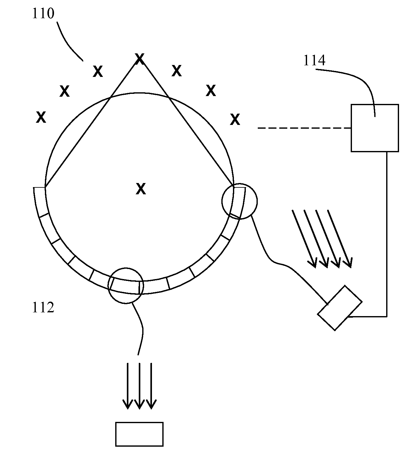
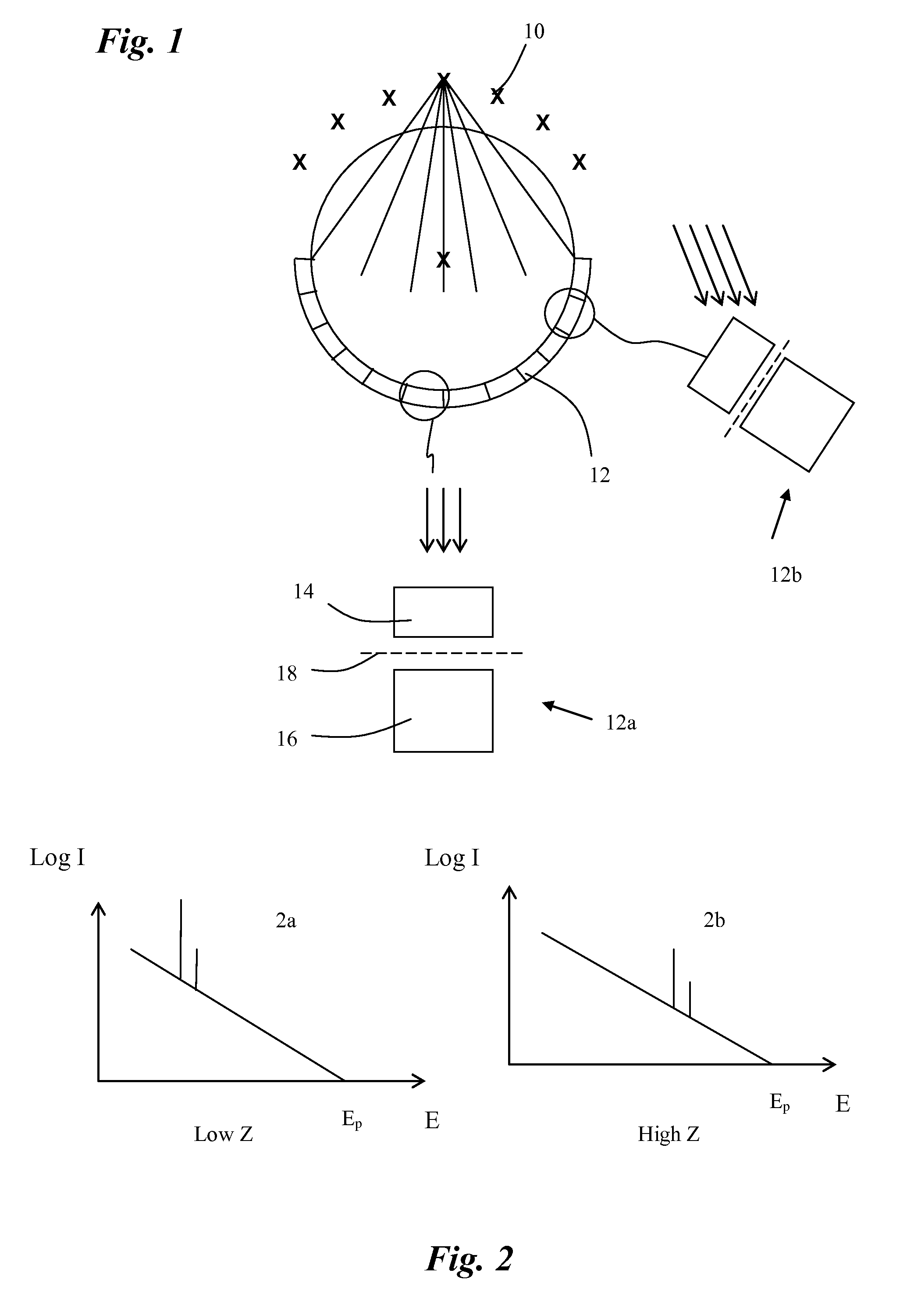
[0040]Referring to FIG. 1, an X-ray scanner comprises a ring array of X-ray sources 10, offset axially from a ring array of X-ray detectors 12. Each of the sources 10 is activated in turn and, for each source, the signals from the detectors 12 are stored and analysed. Each of the sensors is a known stacked sensor comprising a thin front detector element 14 in front of a thicker rear detector element 16, with a filter 18 between the two detector elements. The front detector element 14 is arranged to detect lower energy X-rays, the rear detector element 16 is arranged to detect higher energy X-rays, and the filter 18 is arranged to filter out the lower energy X-rays not absorbed by the front detector element 14.

[0041]Since all of the detectors are aligned with, and face, the axis X of the scanner, it will be seen that at the centre of the X-ray beam, a stacked detector 12a works well in that the front detector element 14, filter 18 and rear detector element 16 are all aligned with the...


PUM


Abstract

The present invention is directed toward an X-ray scanner that has an electron source and an anode. The anode has a target surface with a series of material areas spaced along it in a scanning direction. The material areas are formed from different materials. The electron source is arranged to direct electrons at a series of target areas of the target surface, in a predetermined order, so as to generate X-ray beams having different energy spectra.

Description

CROSS-REFERENCE[0001]The present invention is a continuation-in-part of U.S. patent application Ser. No. 12 / 097,422, filed on Jun. 13, 2008, which is a national stage application of PCT / GB06 / 04684, filed on Dec. 15, 2006, which relies on Great Britain Patent Application Number 0525593.0, filed on Dec. 16, 2005, for priority.[0002]The present application also relies on Great Britain Patent Application No. 0904236.7, filed on Mar. 12, 2009, for priority.[0003]All of the aforementioned applications are incorporated herein by reference.FIELD OF THE INVENTION[0004]The present invention relates to X-ray scanners and in particular to scanners arranged to use different energies of X-rays for use, for example, in the imaging or analysis of objects.BACKGROUND[0005]A new generation of multi-focus X-ray tubes are now being designed to address problems in imaging systems which involve rapid movement of the object under inspection. This is particularly important in tomographic imaging systems whe...

Claims


Application Information

Patent Timeline
Patent Type & Authority Applications(United States)
IPC IPC(8): H01J35/08H01J35/00
CPCG01N23/06G01N2223/206G01V5/00H01J2235/088G01N23/046H01J35/08H01J2235/086H01J35/112A61B6/4042A61B6/482G01N23/087
Inventor MORTON, EDWARD JAMES
Owner RAPISCAN SYST INC (US)
Why Eureka
Try Eureka