Core Hole Drilling Machine

Active Publication Date: 2010-01-28
C & E FEIN
View PDF17 Cites 16 Cited by
  • Summary
  • Abstract
  • Description
  • Claims
  • Application Information

AI Technical Summary

Benefits of technology

[0038]This leads to a further improvement with respect to labor safety. Additionally, the magnetic force sensor may be coupled to the

Problems solved by technology

It has been found in operation that operator errors happen again and again in that the electromagnet sometimes is switched off when the electric motor is still running so that the holding force then no longer suffices to hold the relatively heavy dr

Method used


Image

  • Core Hole Drilling Machine
  • Core Hole Drilling Machine

Examples


Embodiment Construction

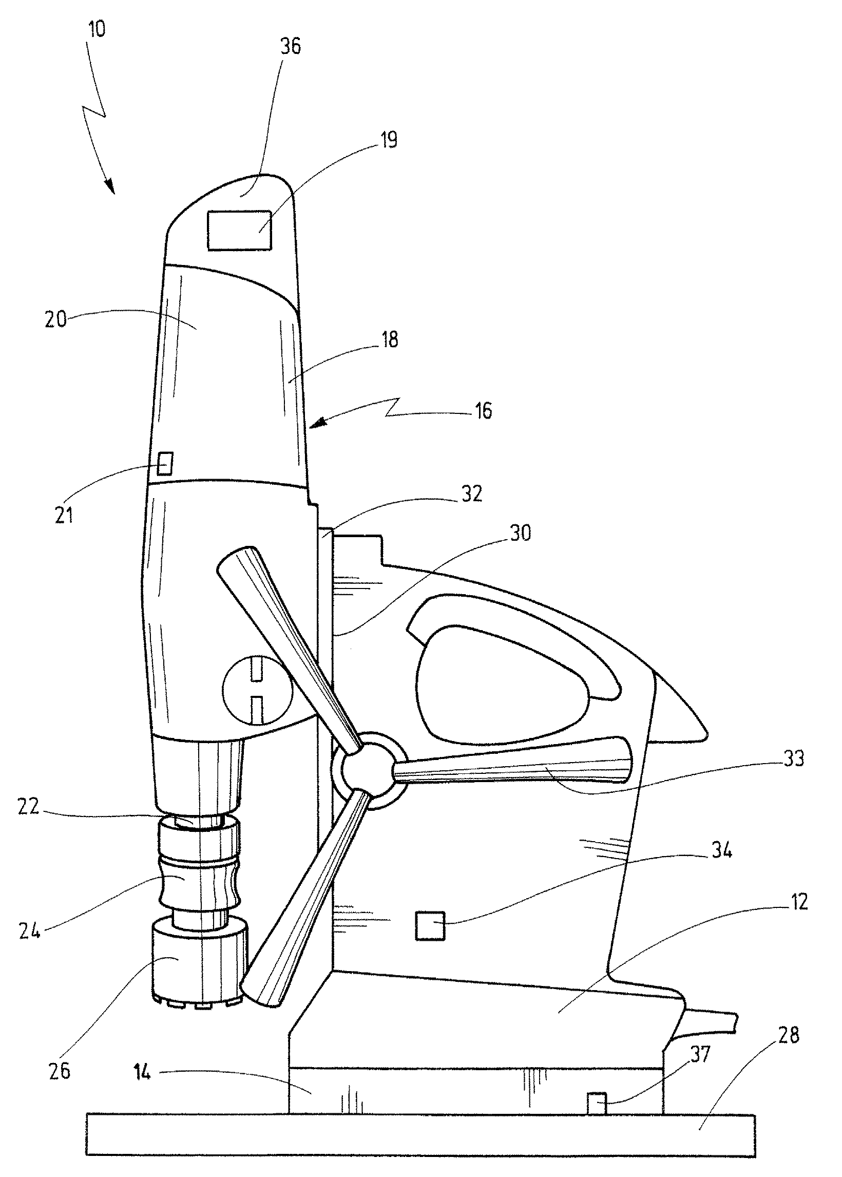
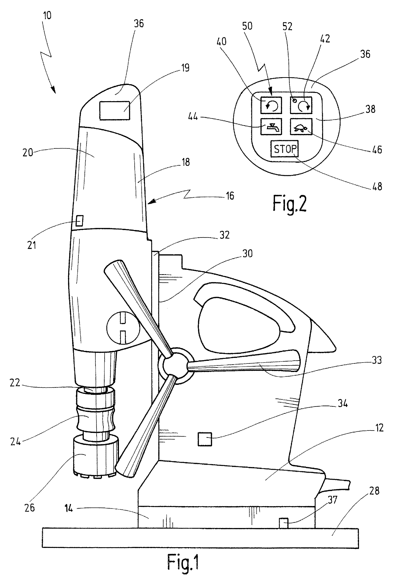
[0043]In FIG. 1 a drilling machine according to the invention in the form of a core hole drilling machine is indicated generally by reference numeral 10.

[0044]The drilling machine 10 comprises a mount 12 that can be fixed on a ferromagnetic metal part 28 by an electromagnet 14. The mount 12 is provided with a guide 30 on which a drilling unit 16 can be displaced via a carriage 32.

[0045]The drilling unit 16 comprises a housing 18 which accommodates an electric motor 20 designed for driving a drilling spindle 22. A drilling tool 26 is detachably mounted on the outer end of the drilling spindle 22 via a fixture 24. Further, the housing 18 accommodates a control 19, preferably designed as a microprocessor control. The control 19 comprises a controller that includes a magnetic switch 34 mounted on the side of the mount 12 and that is designed for switching on and off the electromagnet 14 and the electric motor 20, as will be described in more detail hereafter.

[0046]The controller further...


PUM

PropertyMeasurementUnit
Forceaaaaaaaaaa
Speedaaaaaaaaaa

Abstract

A drilling machine, in particular a core hole drilling machine, having a mount on which an electromagnet is provided for attachment to a metal part on which a drilling unit is supported in displaceable fashion, wherein the drilling unit has a housing that accommodates an electric motor for driving a tool, is provided. There is provided a controller having at least one switch for switching on and off the electric motor and the electromagnet. The controller includes an operating and supervisory panel that is supported on an end of the housing opposite the tool. The switch for switching on and off the electromagnet and for switching off the electric motor is designed so that in the activated condition of the electric motor any operation of the controller will first cause the electric motor to be switched off before the electromagnet can be switched off.

Description

CROSS-REFERENCE TO RELATED APPLICATIONS[0001]The present application claims priority of German patent application No. 10 2008 035 308.6 filed on Jul. 23, 2008, the content of which is incorporated herein by reference.FIELD OF THE INVENTION[0002]The present invention relates to a drilling machine, in particular a core hole drilling machine, having an electromagnet that is to be attached to a metal part, an electric motor for driving a tool and a controller that comprises at least one switch for switching on and off the electric motor and the electromagnet. The invention further relates to a method for controlling such a drilling machine.BACKGROUND OF THE INVENTION[0003]A drilling machine and a method of the before-mentioned kind are known from EP 1 103 350 A2.[0004]One monitors in that case the power-on condition of an electric motor for driving a tool and an electromagnet that is intended to be attached to a ferromagnetic tool. The current of the electromagnet is reduced in a holdin...

Claims


Application Information

Patent Timeline
IPC IPC(8): B23B47/00B23B49/00B23B51/06
CPCB25H1/0071Y10T408/21Y10T408/16Y10T408/44Y10T408/165Y10T408/554
Inventor BEICHTER, MARTIN
Owner C & E FEIN
Why Eureka
Try Eureka