Fan structure for mounting in a light steel structure of a ceiling

a technology of light steel structure and fan structure, which is applied in the direction of machines/engines, liquid fuel engines, positive displacement liquid engines, etc., can solve the problems of reducing the amount of suction air, obstructing the planar beauty of the ceiling, and lowering the performance of the fan structur

Inactive Publication Date: 2010-01-28
YEH TIEN BAO
View PDF11 Cites 15 Cited by
  • Summary
  • Abstract
  • Description
  • Claims
  • Application Information

AI Technical Summary

Benefits of technology

[0007]The present invention has been accomplished to provide a fan structure suitable ...

Problems solved by technology

However, these two prior art designs commonly have a bottom cover suspending below the elevation of the ceiling that obstructs the planar sense of beauty of the ceiling.
Except the problem of sense of beauty, this ...

Method used


Image

  • Fan structure for mounting in a light steel structure of a ceiling
  • Fan structure for mounting in a light steel structure of a ceiling
  • Fan structure for mounting in a light steel structure of a ceiling

Examples


first embodiment

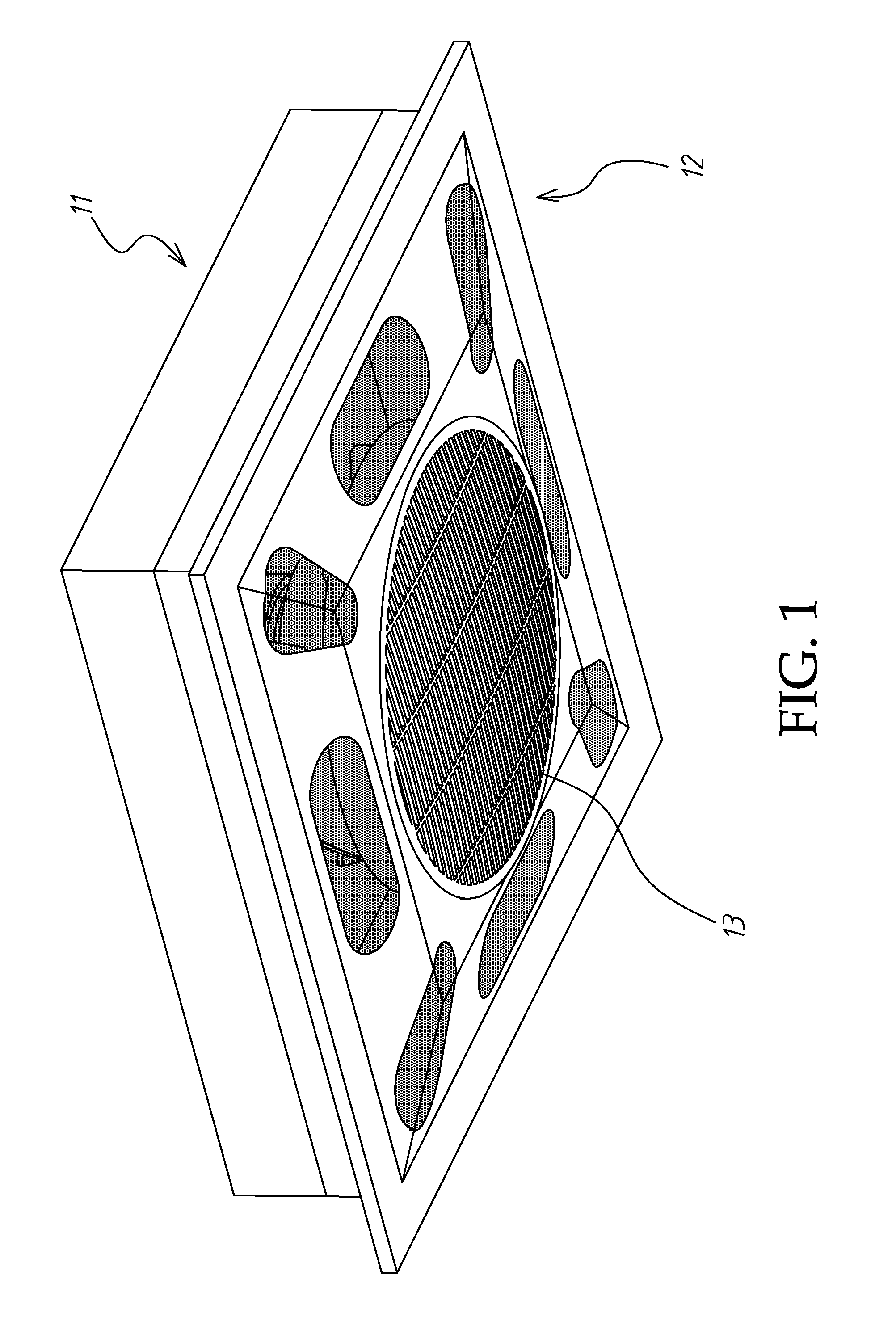
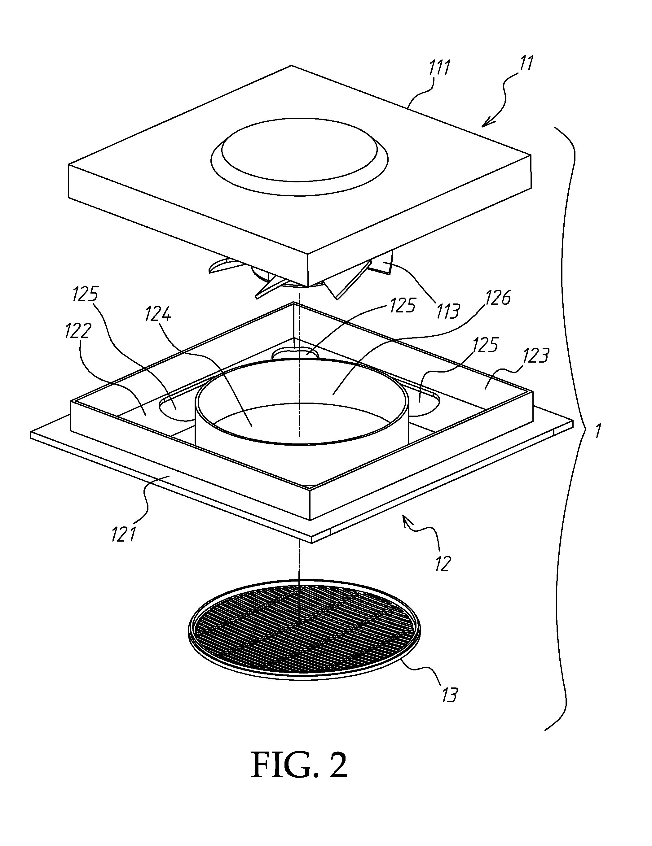
[0022]Referring to FIG. 5, a fan structure 1 is shown mounted in one frame sash of a light steel structure 2 of a ceiling 3. The fan structure 1 in accordance with the present invention, as shown in FIGS. 1˜3, is comprised of a fan holder 11, a bottom cover frame 12, and a grille 13.

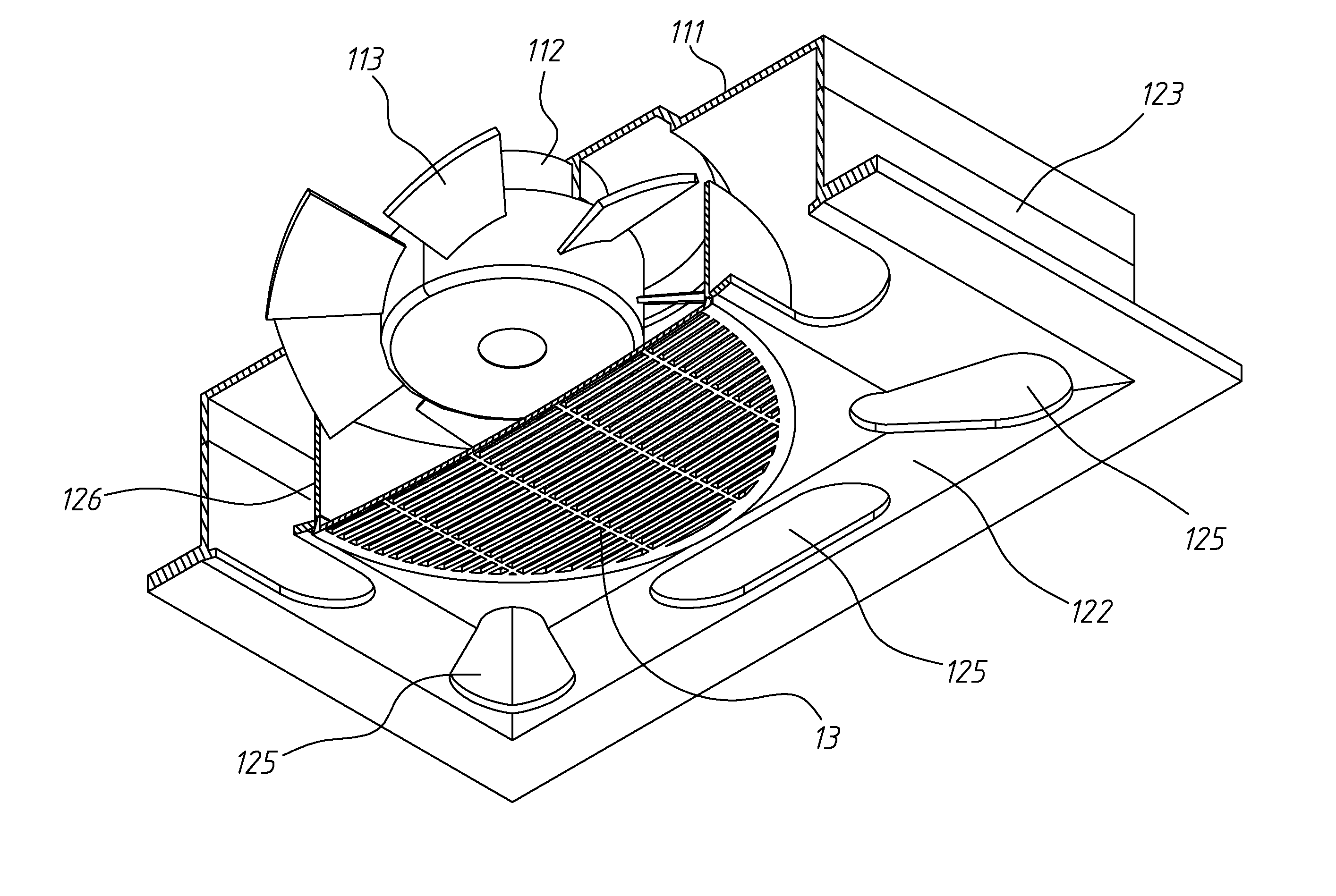
[0023]The fan holder 11 comprises a top cover shell 111, a fan motor 112 mounted in the bottom side of the top cover shell 111, and a fan blade 113 coupled to the output shaft of the fan motor 112 and rotatable by the fan motor 112 to cause currents of air.

[0024]The bottom cover frame 12 comprises a smoothly arched bottom wall 122 curving smoothly downwards, a horizontal mounting flange 121 extending around the smoothly arched bottom wall 122 to facilitate installation of the fan structure 1 in one frame sash of the light steel structure 2 of the ceiling 3, a vertical connection flange 123 upwardly extending from the connection between the smoothly arched bottom wall 122 and the horizontal mounting flang...

second embodiment

[0036]Referring to FIG. 8, when the fan motor 112 of the fan structure 1 according to this second embodiment is electrically connected to rotate the fan blade 113, currents of air (see flow lines in the drawing) are produced to go from the outside into the inside of the bottom cover frame 12 through the ventilation holes 125 of the smoothly arched bottom wall 122 over the fence 126 and then to go toward the outside of the bottom cover frame 12 through the open spaces in the grille 13. At the same time, regulated cold air or hot air is continuously delivered out of the fan duct 4 and moved with the currents of air caused by the fan blade 113 through the grille 13 toward the indoor space.

[0037]FIG. 10 shows a fan structure in accordance with a third embodiment of the present invention. This third embodiment is substantially similar to the aforesaid second embodiment with the exception that the top cover shell 111 of the fan holder 11 of this third embodiment eliminates the aforesaid m...


PUM


Abstract

A fan structure is disclosed to include a fan holder holding a fan motor and a fan blade, a bottom cover frame, which has smoothly arched bottom wall, a horizontal mounting flange extending around the smoothly arched bottom wall and mounted in one frame sash of a light steel structure of a ceiling, a vertical connection flange connected to the top cover shell of the fan holder, a circular center opening corresponding to the fan blade, ventilation holes spaced around the circular center opening and a fence disposed above the circular center opening and surrounding the fan blade defining with the top cover shell of the fan holder a space for causing a gate effect during rotation of the fan blade, and a grille mounted in the circular center opening of the bottom cover shell for output of currents of air caused by the fan blade.

Description

BACKGROUND OF THE INVENTION[0001]1. Field of the Invention[0002]The present invention relates to a fan structure and more particularly, to such a fan structure suitable for mounting in a light steel structure of a ceiling.[0003]2. Description of the Related Art[0004]A light steel structure may be installed in a ceiling inside a room of a building to provide frame sashes for the mounting of ceiling panels or lighting fixtures. Further, a fan structure may be installed in one frame sash of a light steel structure in a ceiling for causing currents of air.[0005]Many light steel structure mountable fan structure designs have been disclosed and have appeared on the market. Exemplars are seen in Taiwan patent number M251939 entitled “IMPROVED FAN STRUCTURE FOR MOUNTING IN A LIGHT STEEL STRUCTURE” and M322475, entitled “IMPROVED FAN STRUCTURE FOR MOUNTING IN A LIGHT STEEL STRUCTURE”. These two prior art designs commonly have an enclosed base disposed at the top side to prevent suction of du...

Claims


Application Information

Patent Timeline
IPC IPC(8): F01D25/28F04D13/06F01D25/24
CPCF04D25/12
Inventor YEH, TIEN-BAO
Owner YEH TIEN BAO
Why Eureka
Try Eureka