Assay plates, methods and systems having one or more etched features

a technology of etched features and plate, applied in the field of plate components, kits, etc., can solve the problems of non-adherent or motile cells migrating between the wells, and achieve the effects of high content screening, high throughput screening, and high throughput screening

Inactive Publication Date: 2010-01-28
LIFE BIOSCI
View PDF11 Cites 58 Cited by
  • Summary
  • Abstract
  • Description
  • Claims
  • Application Information

AI Technical Summary

Benefits of technology

[0011]One embodiment of the present invention provides a high throughput screening device that can be used in drug discovery, protein analysis, ELISA, Antibody based microarray, qPCR, RT-PCR, FRET, cell based assays, High Throughput Screening and High Content Screening, electrochemistry and other medical and biological research.
[0012]The present invention provides a device that includes a high density number of wells located within a set area, such as a standard microtiter plate or microscope slide format, created from APEX glass, ORACLE glasses, plastics, other glasses, or other manufacturable materials.
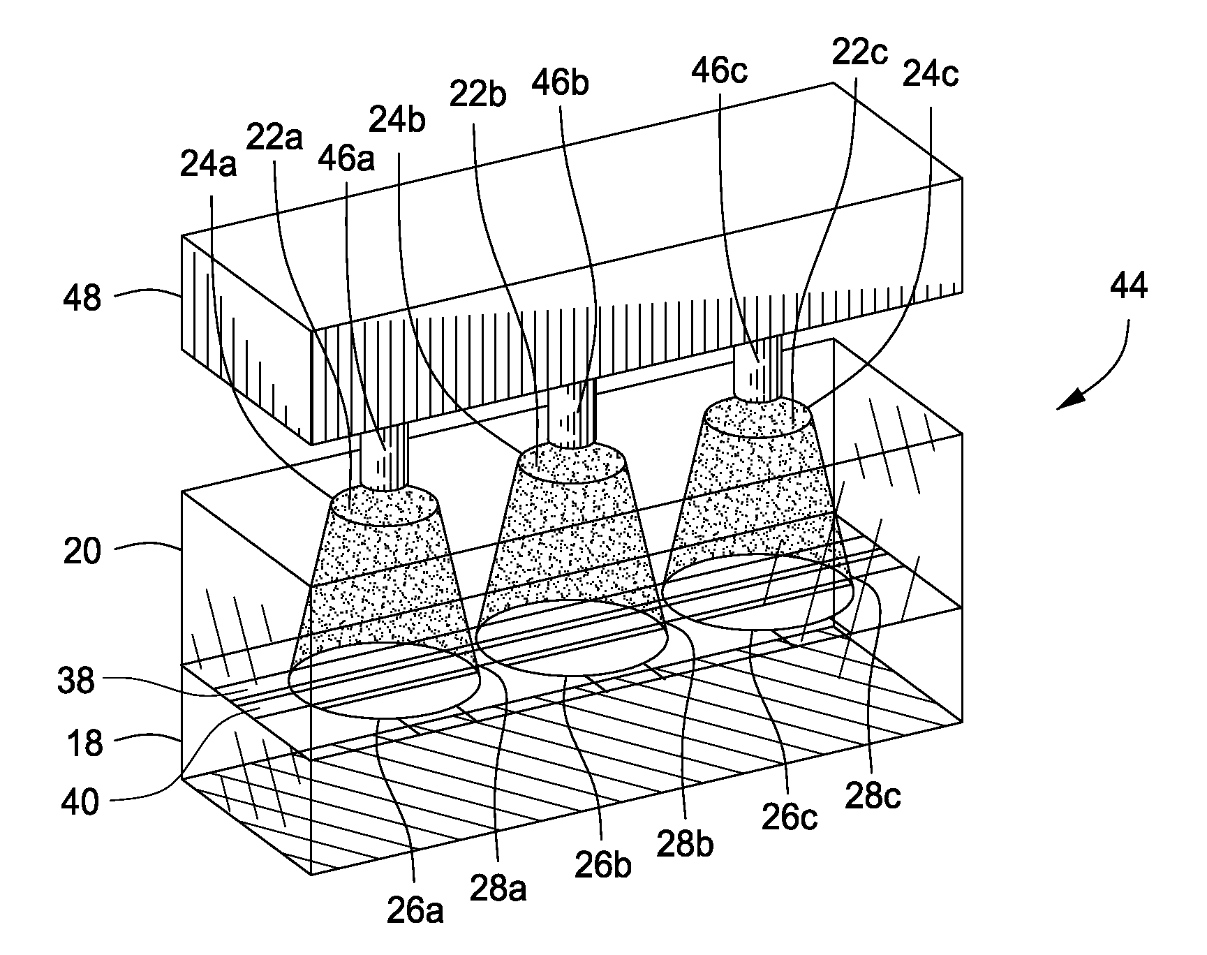
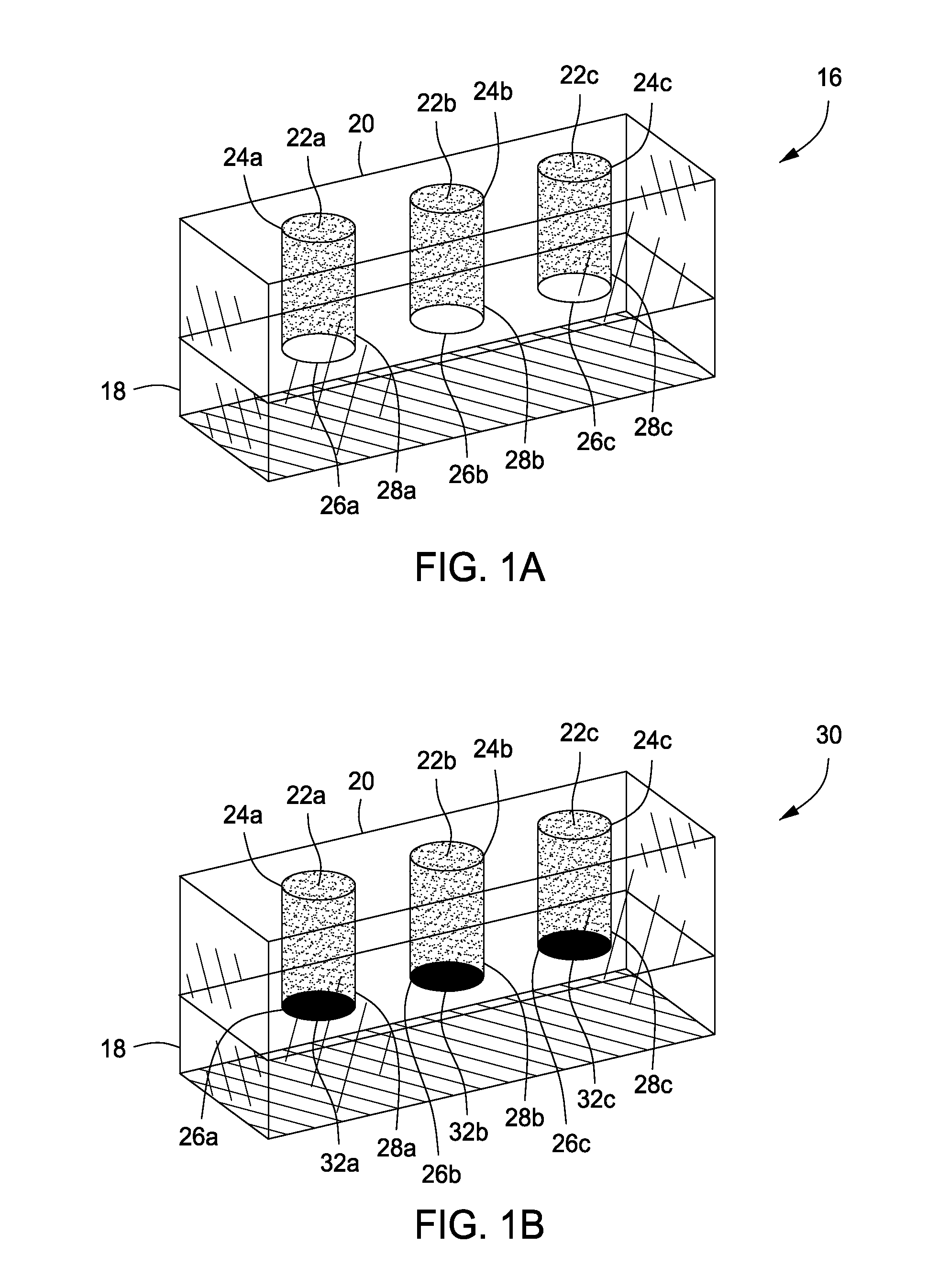
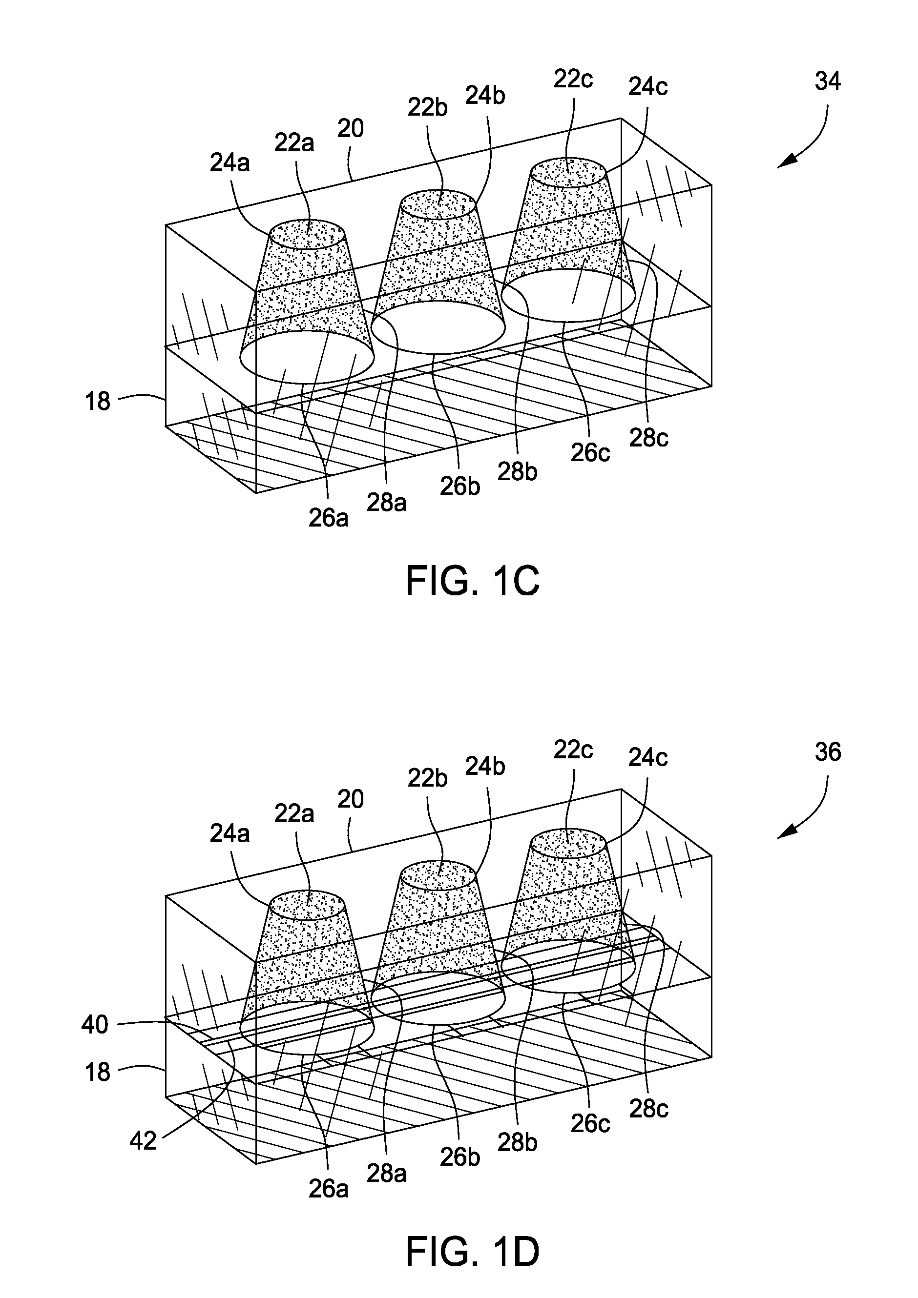
[0013]The present invention provides a multi-well plate having a first layer at least partially disposed on the substrate and one or more nano-wells that extends through the first layer that extends toward the substrate, wherein the one or more nano-wells comprising an opening in the first layer connected to bottom layer by one or more walls.
[0014]The present invention also includes a nano-array plate having a first layer at least partially disposed on a substrate with one or more nano-wells that extends through the first layer that extends toward the substrate. The one or more nano-wells comprising an opening in the first layer connected to bottom layer by one or more walls and one or more micro-posts or micro-Needles extending upwardly from the bottom of the nano-well or extending downwardly from a separate substrate into at least one or more of the nano-wells, or a combination thereof.
[0015]The present invention includes a method of forming a nano-array titer plate by providing a first layer in contact with a substrate and forming one or more nano-wells in the first layer to form a nano-array titer plate, wherein each of the one or more nano-wells comprise an opening connected to a bottom layer by one or more side walls. The nano-array titer plate comprising more than 1,000 nano-wells. The substrate is formed by positioning a working electrode at a first depth in the substrate, covering the working electrode with a passive layer, uncovering a portion of the passive layer that corresponds to the one or more nano-wells, positioning a second electrode in proximity to the working electrode and bonding the substrate to the first layer. One or more micro-posts or micro-Needles may be made to extending upwardly from the bottom of at least one of the one or more nano-wells, or extending downwardly from a separate substrate into at least one or more of the nano-wells, or a combination thereof, with each of the one or more nano-wells are between about 150 microns and 1000 microns in diameter and each of the one or more micro-posts or micro-Needles are between about 25 and 100 microns.
[0016]The present invention also includes a method of measuring electrode induced property in a nano-well assay array having more than 100,000 nano-wells by providing a nano-well assay array, providing electrical energy to the first electrode, the second electrode or both the first and second electrodes and measuring electrode induced property generated in each of the more than 100,000 nano-wells. The nano-well assay array includes a first layer at least partially disposed on a substrate, more than 100,000 nano-wells that extend through the first layer toward the substrate, wherein each of the more than 100,000 nano-wells comprising an opening in the first layer connected to bottom layer by one or more walls and a first electrode and a second electrode within the more than 100,000 nano-wells.

Problems solved by technology

In addition, nonadherent or motile cells may migrate between the wells again contaminating wells.

Method used


Image

  • Assay plates, methods and systems having one or more etched features
  • Assay plates, methods and systems having one or more etched features
  • Assay plates, methods and systems having one or more etched features

Examples


Embodiment Construction

[0031]While the making and using of various embodiments of the present invention are discussed in detail below, it should be appreciated that the present invention provides many applicable inventive concepts that can be embodied in a wide variety of specific contexts. The specific embodiments discussed herein are merely illustrative of specific ways to make and use the invention and do not delimit the scope of the invention.

[0032]To facilitate the understanding of this invention, a number of terms are defined below. Terms defined herein have meanings as commonly understood by a person of ordinary skill in the areas relevant to the present invention. Terms such as “a”, “an” and “the” are not intended to refer to only a singular entity, but include the general class of which a specific example may be used for illustration. The terminology herein is used to describe specific embodiments of the invention, but their usage does not delimit the invention, except as outlined in the claims.

[...


PUM

PropertyMeasurementUnit
diameteraaaaaaaaaa
diameteraaaaaaaaaa
diameteraaaaaaaaaa

Abstract

The present invention includes composition, methods of making and methods of using a multi-nano-well plate having a first layer at least partially disposed on the substrate and one or more nano-wells that extends through the first layer that extends toward the substrate, wherein the one or more nano-wells having an opening in the first layer connected to bottom layer by one or more walls.

Description

CROSS-REFERENCE TO RELATED APPLICATIONS[0001]This application claims priority to U.S. Provisional Application Ser. No. 61 / 083,843, filed Jul. 25, 2008, the contents of which is incorporated by reference herein in its entirety.TECHNICAL FIELD OF THE INVENTION[0002]The present invention relates in general to the field of plates, plate components, kits, apparatuses and methods for conducting chemical, biochemical and / or biological assays.BACKGROUND OF THE INVENTION[0003]Without limiting the scope of the invention, its background is described in connection with methods, compositions and devices used in chemical, biochemical and / or biological assays and more specifically nano-well titer plates.[0004]There have been numerous methods and systems developed for conducting chemical, biochemical and / or biological assays for use in a variety of applications including medical diagnostics, food and beverage testing, environmental monitoring, manufacturing quality control, drug discovery and basic...

Claims


Application Information

Patent Timeline
Patent Type & Authority Applications(United States)
IPC IPC(8): C40B60/12C23F1/00G01R27/28
CPCB01J2219/00317B01L2300/12B01J2219/00511B01J2219/00527B01J2219/00605B01J2219/00612B01J2219/00621B01J2219/00637B01J2219/00648B01J2219/0072B01J2219/00722B01J2219/00725B01J2219/00729B01J2219/0074B01J2219/00743B01L3/5085B01L2200/0689B01L2200/141B01L2200/142B01L2300/0636B01L2300/0645B01L2300/0654B01L2300/0848B01L2300/0893B01J2219/00509
Inventor FLEMMING, JEB H.BUCKLEY, COLIN T.RIDGEWAY, BLAKE
Owner LIFE BIOSCI
Why Eureka
Try Eureka