Heart valve prosthesis

a heart valve and prosthesis technology, applied in the field of medical devices, can solve the problems of increasing the overall dimension of the prosthesis and the risk of restricting the leaflet mobility by the internal heart structure, and achieve the effects of facilitating quick leaflet pivoting and valve closure, and reducing the risk of reducing the overall size of the prosthesis

Active Publication Date: 2010-01-28
MEDENG
View PDF5 Cites 44 Cited by
  • Summary
  • Abstract
  • Description
  • Claims
  • Application Information

AI Technical Summary

Benefits of technology

[0017]The provision of the surfaces, which interact with the leaflet slots at the lateral sides of the console projections of the housing and form the supporting part of the hinge, and the counterpart surfaces, which face the side surfaces of the corresponding console projection of the housing and form the mobile part of the hinge at the inner slot sides, allows the leaflet to pivot around the hinge axis between the open and closed positions. Thus fulfilling the major intended function of the valve, i.e. to pass the direct blood flow and restrict the blood backflow.
[0018]The provision of the mainly cylindrical inner surface of the housing together with the downstream surface of each leaflet in the form of crossing cylindrical and conical surfaces with the diameter equal to the diameter of the inner surface of the housing ensures mutual conformity of said surfaces. Namely: because the central axis of the cylindrical downstream surface of the leaflet in the open position is parallel to the central axes of the housing, its cylindrical downstream surface fits closely to the inner surface of the housing practically along its whole perimeter, thus preventing the possibility of generation of any obstacles to the blood flow. Because the other part of the cylindrical downstream surface is conical it provides a surface inclined to the flow axis, which facilitates quick leaflet pivoting and valve closure under the influence of the blood backflow. The proposed embodiment of the downstream leaflet surface is an optimal one, but, without restricting the subject matter of the invention, it may be formed with other surfaces, for example, spherical, toroidal, conical ones, or in the form of two crossing cylindrical surfaces.
[0019]The provision of the upstream surface of each leaflet in the form of the cylindrical surface with the diameter equal or somewhat bigger than that of the inner surface of the housing ensures creation of the approximately cylindrical hydraulic orifice which allows the direct blood flow to pass freely through it when the leaflets are in the open position. The provision of the central axis of the upstream cylindrical surface of the leaflet in the open position approximately parallel to the central axis of the housing prevents creation of the extra orifice confuserness which can lead to additional energy losses.
[0020]The provision of the ledges at the inner surface of the housing, which interact with the side surfaces of the leaflets in the closed position, prevents leaflet escape from the housing.
[0021]Said features of the prosthesis ensure the creation of positive effect, that is a higher thromboresistance, better structure of the blood flow, and less trauma to formed elements of the blood.

Problems solved by technology

However, its leaflets, which divide the hydraulic orifice of the housing into three segments, disrupt the homogeneous laminar structure of blood flow with creation of blood stagnation zones and thus preserving the possibility of thrombotic complications.
However the provision of the leaflet pivoting limiters at the end surface of the housing increases the prosthesis overall dimensions and risk of restriction of leaflet mobility by the internal heart structures.

Method used


Image

  • Heart valve prosthesis
  • Heart valve prosthesis
  • Heart valve prosthesis

Examples


Embodiment Construction

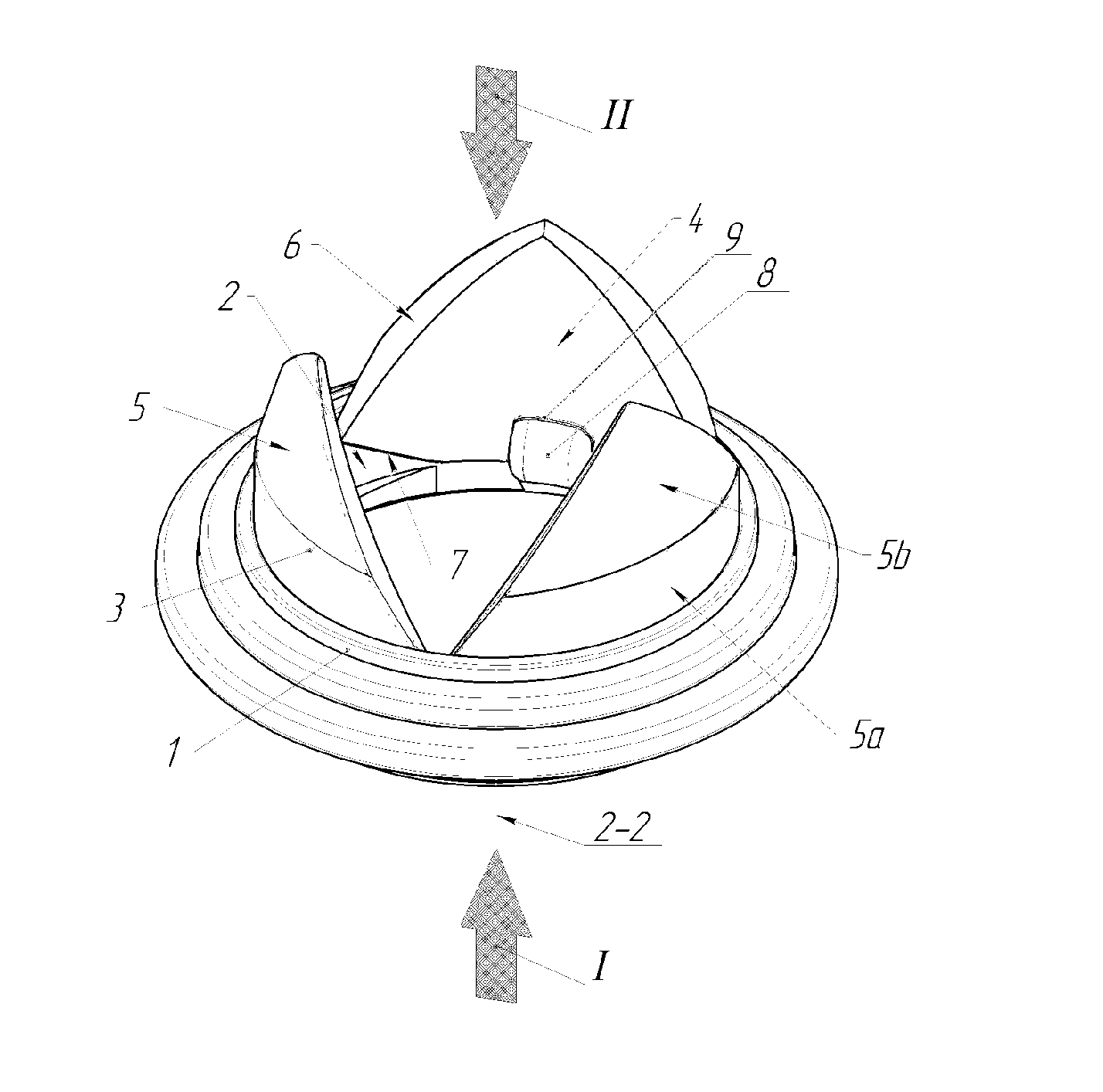
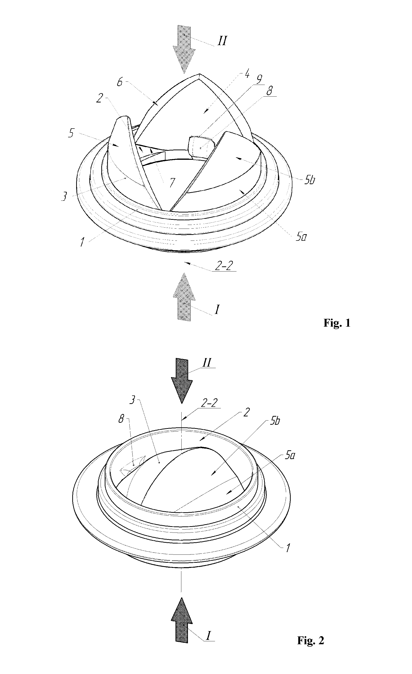
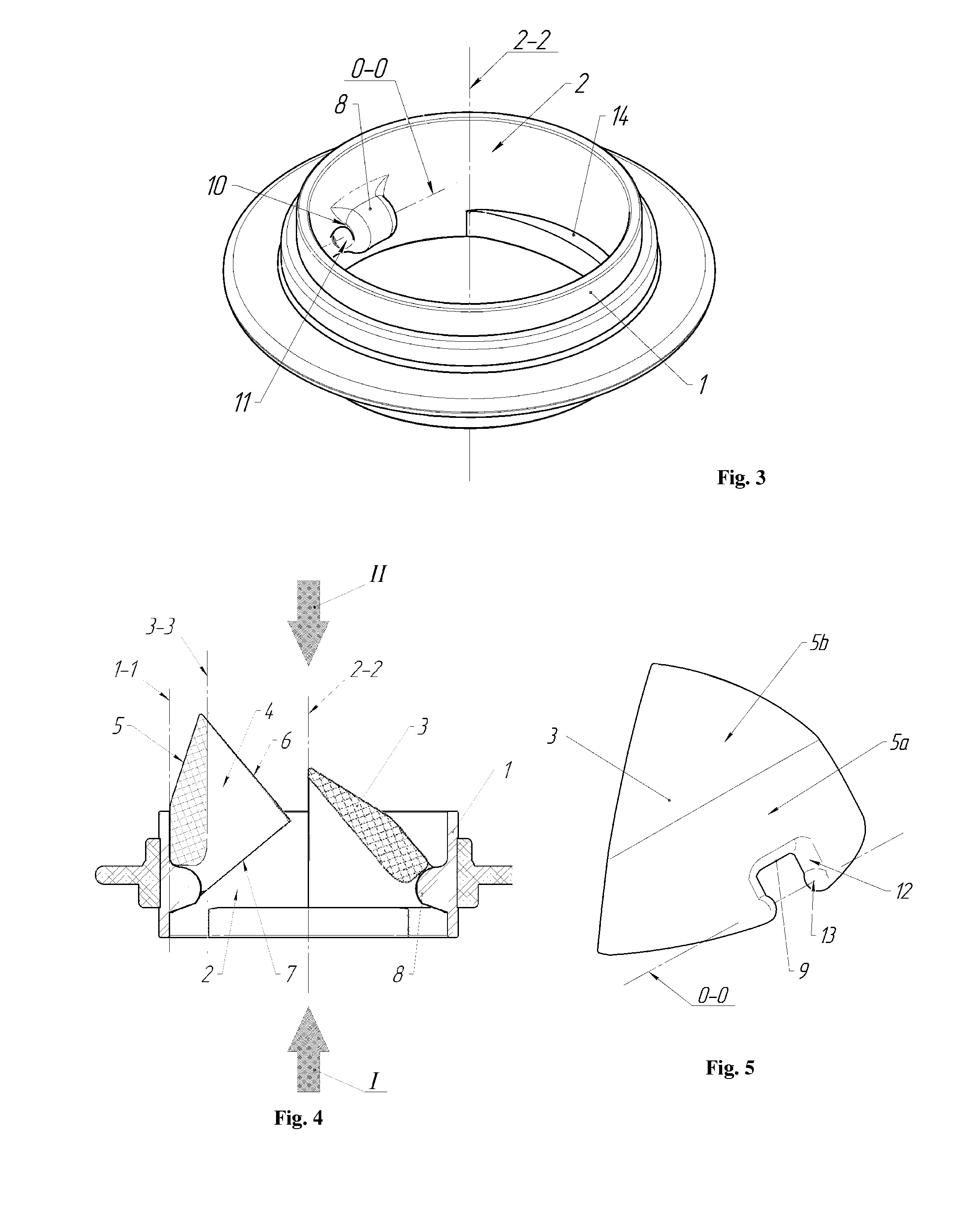
[0027]For convenience in the drawings the direct blood flow is shown by the arrow I and the blood backflow by the arrow II.

[0028]The heart valve prosthesis comprising of the annular housing 1 with the inner surface 2, defining the blood flow I through the valve prosthesis, and the leaflets 3 mounted within the annular housing 1 with the possibility to pivot around the reference axis of rotation (shown by the dash-and-dot line 0-0) between the open position, which allows the passage of the direct blood flow I, and the closed position which restrict the blood backflow II. Each leaflet 3 has the upstream surface 4 facing the direct blood flow I, the downstream surface 5 facing the blood backflow II, the coaptation surface 6, and the side surface 7.

[0029]The console projections 8 radially oriented are provided at the inner surface 2 of the housing 1, and the slot 9, which corresponds to the projection, is provided at each leaflet.

[0030]The concave spherical surfaces 11 forming the suppo...


PUM


Abstract

A medical device in cardiac surgery for replacement of the diseased native heart valves in humans increases thromboresistance of heart valve prosthesis. A heart valve prosthesis comprising an annular housing with the inner surface defining the blood flow I through the valve prosthesis and leaflets mounted within the annular housing with the possibility to pivot around the reference axis between an open position which allows the passage of the direct blood flow I, and a closed position which restricts the blood backflow II. Each leaflet has an upstream surface facing the direct blood surface I, a downstream surface facing the blood backflow II, a coaptation surface, and a side surface. Console projections radially oriented are provided at the inner surface of the housing, and each leaflet has a slot which corresponds to the projection. The inner surface of the housing is mainly cylindrical, and the downstream surface of each leaflet is in the form of the crossing cylindrical and conical surfaces. The upstream surface of each leaflet is in the form of the cylindrical surface. Higher thromboresistance of the heart valve prosthesis is achieved through elimination of the elements which introduce disturbances into the blood flow and reduction of the number of hinged joints.

Description

BACKGROUND OF THE INVENTION[0001]The invention relates to medical devices and can be used in cardiac surgery for replacement of the diseased native aortic and mitral heart valves in humans. This invention can also be successfully used for replacement of the diseased tricuspid valve.[0002]There is a certain heart valve prosthesis [1] comprising an annular housing with fixing elements restricted by support surfaces facing the direct and reverse blood flow and a side surface facing the central axis of the housing, and leaflets mounted within the annular housing with the possibility to pivot between an open position, which allows the passage of the direct blood flow, and a closed position which restricts the blood backflow, each leaflet has an outer side surface having projections with support surfaces facing the direct blood flow, which interact with the corresponding support surfaces of said fixing element of the housing, a coaptation surface interacting with the corresponding coaptat...

Claims


Application Information

Patent Timeline
Patent Type & Authority Applications(United States)
IPC IPC(8): A61F2/24
CPCA61F2220/0091A61F2/2403
Inventor EVDOKIMOV, SERGEY VASILYEVICHEVDOKIMOV, ALEXANDR SERGEYEVICHGONCHAROV, EDUARD YURIEVICHFILIPPOV, ALEXANDR NIKOLAYEVICH
Owner MEDENG
Why Eureka
Try Eureka