
Air-conditioning system controller

Inactive Publication Date: 2010-01-28
KK TOSHIBA
View PDF4 Cites 19 Cited by
  • Summary
  • Abstract
  • Description
  • Claims
  • Application Information

AI Technical Summary

Benefits of technology

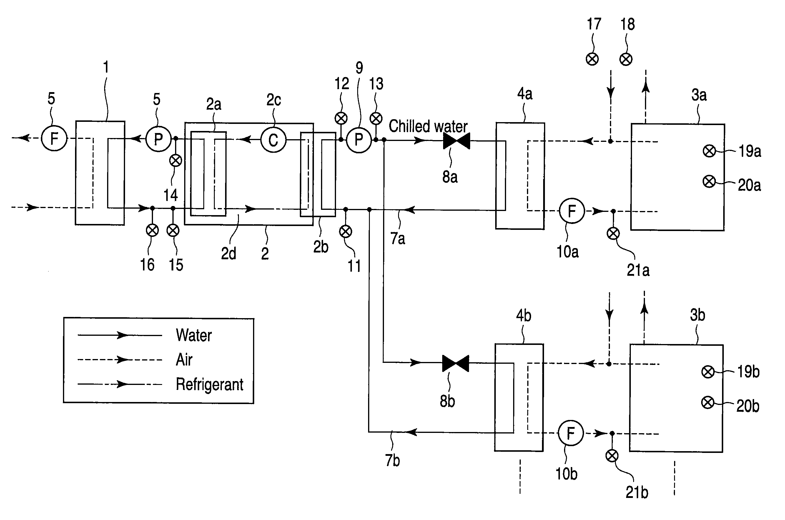
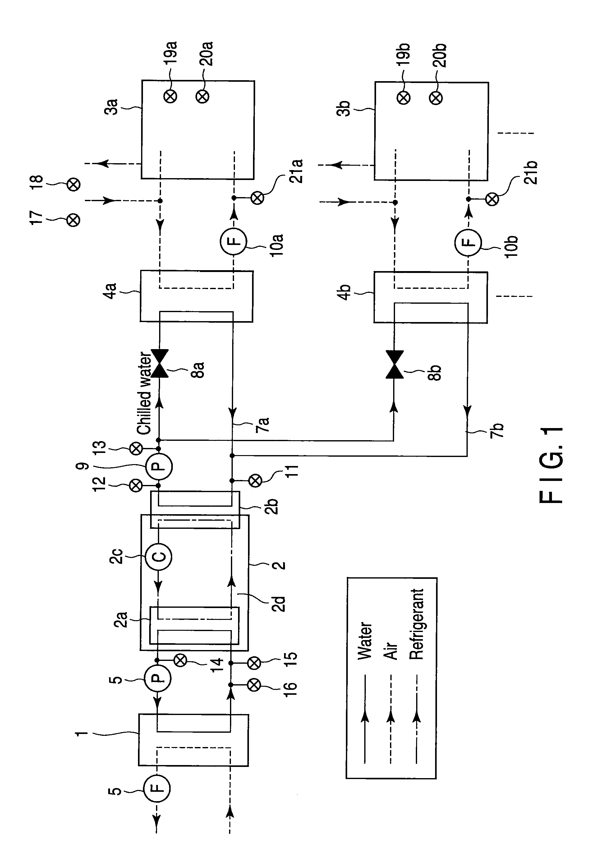
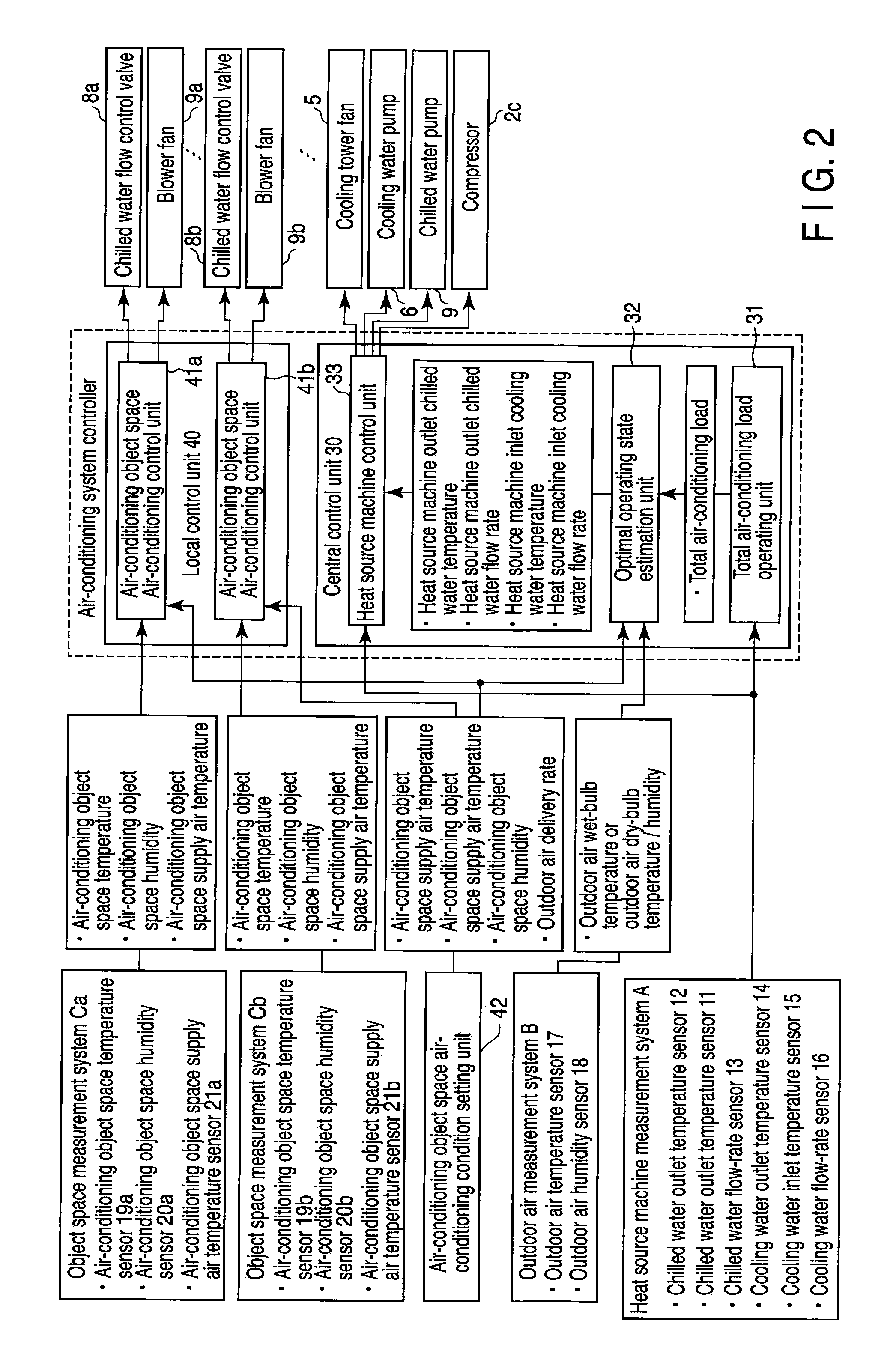
[0018]Accordingly, the object of the present invention is to provide an air-conditioning system controller in which an operating state of an air-conditioning system is determined such that the total required power of air-conditioning equipment constituting the air-conditioning system is minimal, based on at least a total air-conditioning load as an input variable, and each air-conditioning equipment is controlled in accordance with the determined target value, whereby a plurality of air-conditioning object spaces are efficiently air-conditioned so that energy can be saved.

Problems solved by technology

Therefore, these prior art methods can be the to be control methods that do not pursue the maximum energy-saving effect that is thermodynamically feasible but realize partial energy saving.
In this case, however, the air-conditioning load conditions are not taken into consideration, and a plurality of air-conditioning object spaces cannot be efficiently air-conditioned by a single heat source machine, which involve basic problems to be solved.
Thus, optimal control for efficient energy-saving performance is not achieved.

Method used


Image

  • Air-conditioning system controller
  • Air-conditioning system controller
  • Air-conditioning system controller

Examples


Embodiment Construction

[0025]An embodiment of the present invention will now be described with reference to the drawings.

[0026]Before describing the present embodiment, it is generally necessary first, in order to achieve an ideal energy-saving operation of an air-conditioning system, to estimate state quantities, such as optimum temperatures and flow rates of working fluids, e.g., chilled water and air that convey heat, such that the total required power of all air-conditioning equipment constituting the air-conditioning system is minimal, based on the enthalpy balance between the working fluids, mass balance of water vapor in the air, etc., as constraint conditions, and to control the operation of the air-conditioning equipment constituting the air-conditioning system so that actual measured values are coincident with the estimated state quantities.

[0027]Thereupon, premises are designed such that the total air-conditioning load of the air-conditioning system is temporarily estimated by calculating the q...


PUM


Abstract

In an air-conditioning system controller provided with a central control unit and a local control unit, the central control unit includes a heat source machine measurement system for measuring an input / output state of a heat source machine, a setting unit for setting air-conditioning condition data on air-conditioning object spaces, an outdoor air measurement system for measuring outdoor air condition data, a total air-conditioning load operating unit, an optimal operating state estimation unit, and a heat source machine control. The total air-conditioning load operating unit calculates a total air-conditioning load or a heat exchange rate of the heat source machine based on chilled water inlet and outlet temperatures and chilled water flow rate of the heat source machine.

Description

CROSS REFERENCE TO RELATED APPLICATIONS[0001]This is a Continuation Application of PCT Application No. PCT / JP2008 / 050292, filed Jan. 11, 2008, which was published under PCT Article 21(2) in Japanese.[0002]This application is based upon and claims the benefit of priority from prior Japanese Patent Application No. 2007-098551, filed Apr. 4, 2007, the entire contents of which are incorporated herein by reference.BACKGROUND OF THE INVENTION[0003]1. Field of the Invention[0004]The present invention relates to an air-conditioning system controller for controlling an air-conditioning system for cooling or heating a building such as a hospital.[0005]2. Description of the Related Art[0006]In recent years, there has been an increasing demand for energy saving of various types of air-conditioning equipment constituting an air-conditioning system in a building or the like. To meet this demand, a large number of air-conditioning system controllers have been proposed that can reduce the power of ...

Claims


Application Information

Patent Timeline
IPC IPC(8): G05B15/00
CPCF24F11/0009F24F2011/0061F24F2011/0045F24F2011/0013F24F11/30F24F2110/12F24F2140/20F24F11/63F24F11/77F24F11/81F24F11/46F24F11/86F24F11/83
Inventor ITO, YASUYUKITAKAGI, YASUOYONEZAWA, KENZOMURAKAMI, YOSHIKINISHIMURA, NOBUTAKADONEN, NOBUYUKI
Owner KK TOSHIBA
Learn More